
Hydrogen Gas Detection System with MQ-8 Sensor and Arduino UNO R4 WiFi
View and Edit Project In Cirkit Designer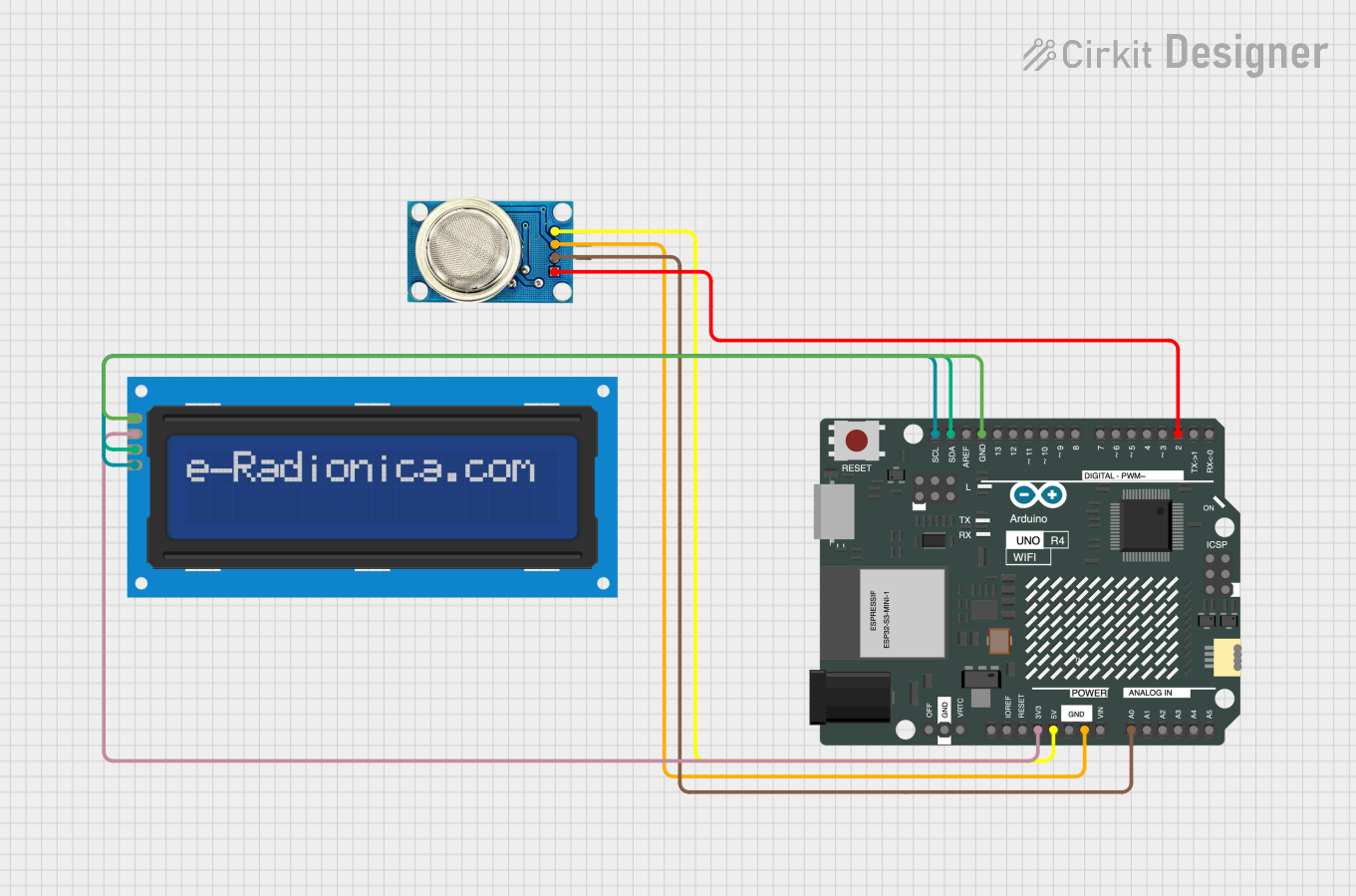
Circuit Documentation
Summary
This circuit is designed to measure hydrogen gas levels using an MQ-8 Hydrogen Gas Sensor and display the results on a 16x2 I2C LCD screen. The circuit is controlled by an Arduino UNO R4 WiFi microcontroller. The MQ-8 sensor provides both analog and digital outputs, which are read by the Arduino and displayed on the LCD screen.
Component List
MQ-8 Hydrogen Gas Sensor
- Description: A sensor used to detect hydrogen gas levels.
- Pins: VCC, GND, AO, DO
Arduino UNO R4 WiFi
- Description: A microcontroller board based on the ATmega328P, with built-in WiFi capabilities.
- Pins: OFF, GND, VRTC, IIC0_SCL, IIC0_SDA, 3V3, GPIO 41, GPIO 0, GPIO 42, GPIO 43, GPIO 44, BOOT, IOREF, RESET, 5V, VIN, A0, A1, A2, A3, A4, A5, RSPCKA, CIPO, COPI, D0/RX, D1/TX, D2, D3, D4, D5, D6, D7, D8, D9, D10, D11, D12, D13, AREF, SDA, SCL
LCD screen 16x2 I2C
- Description: A 16x2 character LCD display with I2C interface.
- Pins: SCL, SDA, VCC, GND
Wiring Details
MQ-8 Hydrogen Gas Sensor
- VCC to Arduino 5V
- GND to Arduino GND
- AO to Arduino A0
- DO to Arduino D2
Arduino UNO R4 WiFi
- 5V to MQ-8 VCC
- GND to MQ-8 GND
- A0 to MQ-8 AO
- D2 to MQ-8 DO
- 3V3 to LCD VCC
- GND to LCD GND
- SDA to LCD SDA
- SCL to LCD SCL
LCD screen 16x2 I2C
- VCC to Arduino 3V3
- GND to Arduino GND
- SDA to Arduino SDA
- SCL to Arduino SCL
Code Documentation
/*
 * Arduino UNO R4 WiFi to measure Hydrogen and display results on LCD screen.
 * Components:
 * - MQ-8 Hydrogen Gas Sensor
 * - LCD screen 16x2 I2C
 * Connections:
 * - MQ-8 VCC to Arduino 5V
 * - MQ-8 GND to Arduino GND
 * - MQ-8 AO to Arduino A0
 * - MQ-8 DO to Arduino D2
 * - LCD VCC to Arduino 3V3
 * - LCD GND to Arduino GND
 * - LCD SDA to Arduino SDA
 * - LCD SCL to Arduino SCL
 */

#include <Wire.h>
#include <LiquidCrystal_I2C.h>

// Initialize the LCD, set the LCD address to 0x27 for a 16 chars and 2 line display
LiquidCrystal_I2C lcd(0x27, 16, 2);

// Define the analog pin for MQ-8 sensor
const int mq8AnalogPin = A0;
// Define the digital pin for MQ-8 sensor
const int mq8DigitalPin = 2;

void setup() {
  // Initialize the LCD
  lcd.begin();
  lcd.backlight();
  // Initialize serial communication
  Serial.begin(9600);
  // Set the digital pin as input
  pinMode(mq8DigitalPin, INPUT);
}

void loop() {
  // Read the analog value from MQ-8 sensor
  int analogValue = analogRead(mq8AnalogPin);
  // Read the digital value from MQ-8 sensor
  int digitalValue = digitalRead(mq8DigitalPin);
  // Print the values to the serial monitor
  Serial.print("Analog Value: ");
  Serial.print(analogValue);
  Serial.print(" Digital Value: ");
  Serial.println(digitalValue);
  // Display the values on the LCD
  lcd.clear();
  lcd.setCursor(0, 0);
  lcd.print("Analog: ");
  lcd.print(analogValue);
  lcd.setCursor(0, 1);
  lcd.print("Digital: ");
  lcd.print(digitalValue);
  // Wait for a second before the next loop
  delay(1000);
}
This code initializes the LCD and sets up the pins for the MQ-8 sensor. In the loop function, it reads the analog and digital values from the MQ-8 sensor, prints them to the serial monitor, and displays them on the LCD screen. The loop runs continuously with a delay of one second between each iteration.