
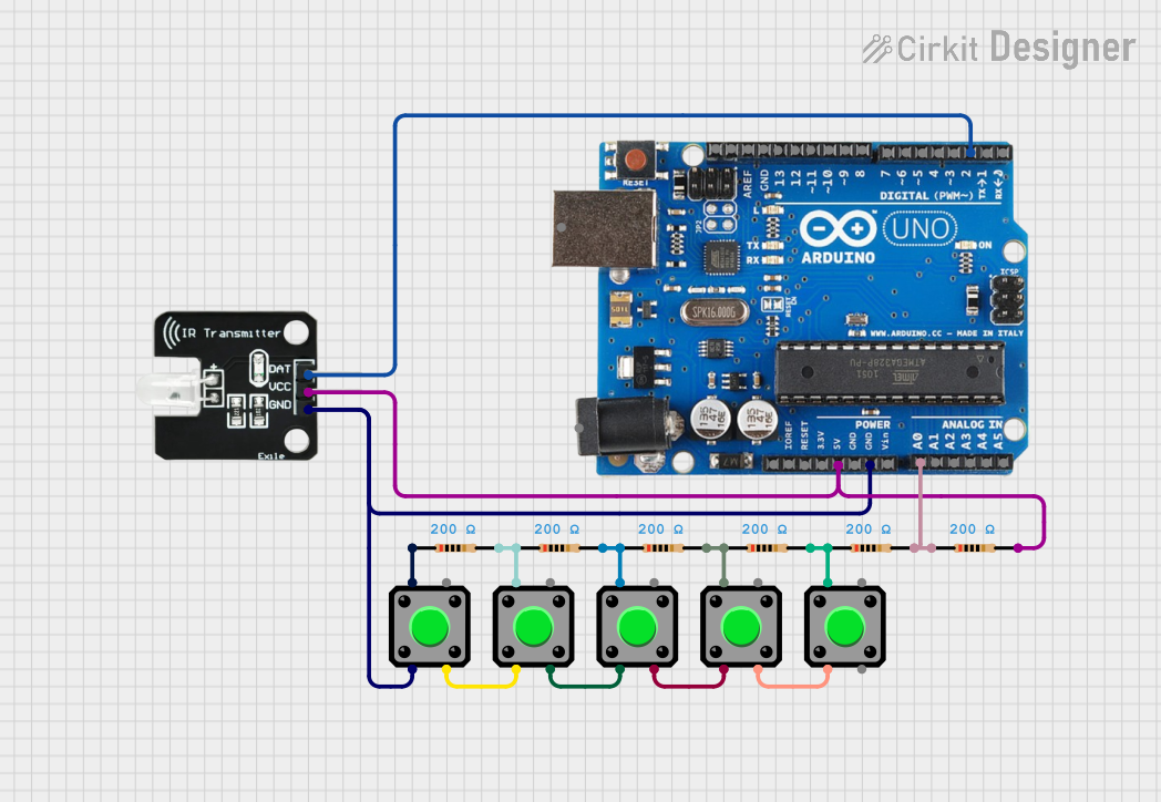
Circuit Documentation
Summary
This circuit is designed to read the voltage from a voltage divider network formed by pushbuttons and resistors. When a button is pressed, the corresponding voltage level is read by an Arduino Uno R3, which then generates an IR code using an IR transmitter. The circuit includes multiple pushbuttons, resistors, an IR transmitter, and an Arduino Uno R3 microcontroller.
Component List
IR Transmitter
- Pins: DAT, VCC, GND
- Description: Transmits infrared signals.
- Purpose in Circuit: Sends IR codes based on the input from the Arduino.
Arduino Uno R3
- Pins: D8, D9, D10, D11, D12, D13, GND, AREF, SDA, SCL, D0/RX, D1/Tx, D2, D3, D4, D5, 6, D7, A5/SCL, A4/SDA, A3, A2, A1, A0, Vin, 5V, 3.3V, RESET, IOREF, NONE, USB Jack, Power Jack
- Description: Microcontroller board based on the ATmega328P.
- Purpose in Circuit: Reads voltage levels from the voltage divider network and sends corresponding IR codes.
Pushbutton
- Pins: Pin 2, Pin 1, Pin 3, Pin 4
- Description: Mechanical switch that can be pressed to make or break a connection.
- Purpose in Circuit: Forms part of the voltage divider network to provide different voltage levels when pressed.
Resistor
- Pins: pin1, pin2
- Description: 200 Ohms resistor.
- Purpose in Circuit: Forms part of the voltage divider network to provide different voltage levels.
Wiring Details
IR Transmitter
- DAT connected to D2 on Arduino Uno R3.
- VCC connected to 5V on Arduino Uno R3 through a resistor.
- GND connected to GND on Arduino Uno R3.
Arduino Uno R3
- D2 connected to DAT on IR Transmitter.
- 5V connected to VCC on IR Transmitter through a resistor.
- GND connected to GND on IR Transmitter and Pin 2 on one of the pushbuttons.
- A0 connected to pin1 of a resistor.
Pushbuttons
- Pin 2 of one pushbutton connected to GND on Arduino Uno R3.
- Pin 2 of another pushbutton connected to Pin 3 of another pushbutton.
- Pin 1 of one pushbutton connected to pin2 of a resistor and pin1 of another resistor.
- Pin 3 of one pushbutton connected to Pin 2 of another pushbutton.
- Pin 1 of another pushbutton connected to pin1 of a resistor.
Resistors
- pin2 of one resistor connected to 5V on Arduino Uno R3 and VCC on IR Transmitter.
- pin1 of the same resistor connected to A0 on Arduino Uno R3 and pin2 of another resistor.
- pin2 of another resistor connected to pin1 of another resistor and Pin 1 of a pushbutton.
- pin1 of another resistor connected to pin2 of another resistor and Pin 1 of another pushbutton.
- pin1 of another resistor connected to pin2 of another resistor and Pin 1 of another pushbutton.
Code Documentation
/*
 * This Arduino sketch reads the voltage from pin A0, which is connected to a
 * voltage divider network formed by pushbuttons and resistors. When a button
 * is pressed, the corresponding voltage level is read, and the Arduino
 * generates an IR code using the IR transmitter connected to pin D2.
 */

#include <IRremote.h>

const int irPin = 2; // IR Transmitter connected to pin D2
const int analogPin = A0; // Voltage divider network connected to pin A0
IRsend irsend;

void setup() {
  pinMode(irPin, OUTPUT);
  Serial.begin(9600);
}

void loop() {
  int analogValue = analogRead(analogPin);
  Serial.print("Analog value: ");
  Serial.println(analogValue);

  if (analogValue < 100) {
    // Button 1 pressed
    irsend.sendNEC(0xFFA25D, 32); // Example IR code
  } else if (analogValue < 200) {
    // Button 2 pressed
    irsend.sendNEC(0xFF629D, 32); // Example IR code
  } else if (analogValue < 300) {
    // Button 3 pressed
    irsend.sendNEC(0xFFE21D, 32); // Example IR code
  } else if (analogValue < 400) {
    // Button 4 pressed
    irsend.sendNEC(0xFF22DD, 32); // Example IR code
  } else if (analogValue < 500) {
    // Button 5 pressed
    irsend.sendNEC(0xFF02FD, 32); // Example IR code
  }

  delay(100); // Debounce delay
}
This code reads the voltage from pin A0, which is connected to a voltage divider network formed by pushbuttons and resistors. When a button is pressed, the corresponding voltage level is read, and the Arduino generates an IR code using the IR transmitter connected to pin D2.