
ESP32 and Arduino UNO Based GPS-Enabled Battery-Powered Smart Relay System
View and Edit Project In Cirkit Designer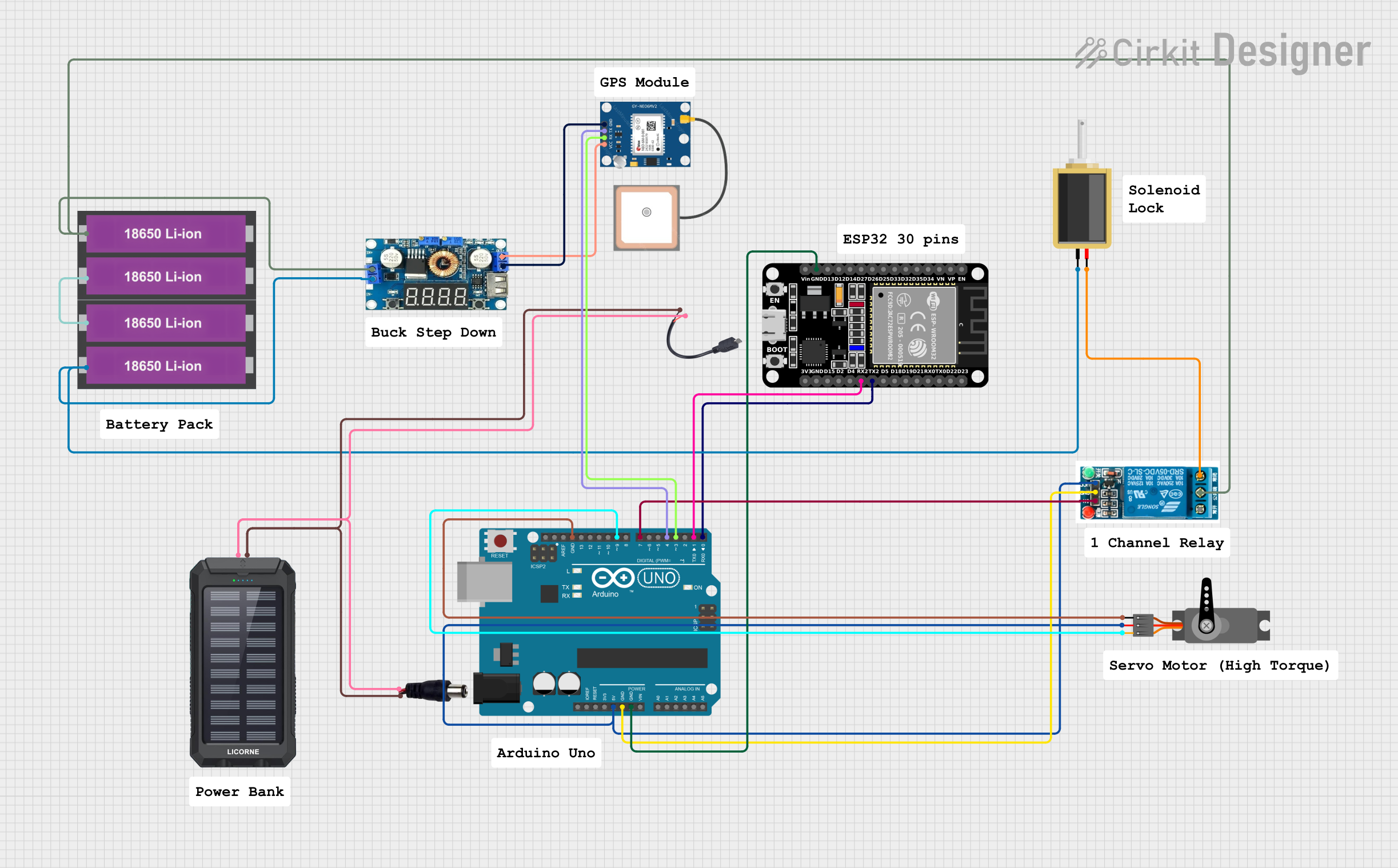
Circuit Documentation
Summary
This document provides a detailed overview of a circuit that integrates an ESP32 microcontroller, an Arduino UNO, a GPS module, a servo motor, a relay, a solenoid, a step-down voltage regulator, and power sources including 18650 Li-ion batteries and a solar charger power bank. The circuit is designed to perform various functions, including GPS tracking, servo control, and relay switching.
Component List
ESP32 (30 pin)
- Description: A powerful microcontroller with built-in Wi-Fi and Bluetooth capabilities.
- Pins: EN, VP, VN, D34, D35, D32, D33, D25, D26, D27, D14, D12, D13, GND, Vin, D23, D22, TX0, RX0, D21, D19, D18, D5, TX2, RX2, D4, D2, D15, 3V3
Arduino UNO
- Description: A popular microcontroller board based on the ATmega328P.
- Pins: UNUSED, IOREF, Reset, 3.3V, 5V, GND, Vin, A0, A1, A2, A3, A4, A5, SCL, SDA, AREF, D13, D12, D11, D10, D9, D8, D7, D6, D5, D4, D3, D2, D1, D0
GPS NEO 6M
- Description: A GPS module used for tracking and navigation.
- Pins: VCC, RX, TX, GND
Regulator Stepdown DC with LCD Display
- Description: A step-down voltage regulator with an LCD display for monitoring output voltage.
- Pins: IN +, IN -, OUT +, OUT -
18650 Li-ion Battery x 2
- Description: Rechargeable lithium-ion batteries.
- Pins: +, -
5v relay
- Description: A relay module used for switching high-power devices.
- Pins: Normally Open, Common terminal, Normally Closed, In, GND, VCC
Solar Charger Power Bank
- Description: A power bank with solar charging capabilities.
- Pins: +, -
Power Jack
- Description: A power jack for connecting external power sources.
- Pins: POSITIF, NEGATIF
Micro USB to Cable (2 Pin)
- Description: A micro USB to 2-pin cable for power connections.
- Pins: Micro USB, +, -
Servo
- Description: A servo motor for precise control of angular position.
- Pins: GND, VCC, PWM
Solenoid
- Description: An electromechanical solenoid for linear actuation.
- Pins: pin1, pin2
Wiring Details
ESP32 (30 pin)
- GND connected to Arduino UNO GND
Arduino UNO
- GND connected to ESP32 GND and 5v relay GND
- D0 connected to ESP32 TX2
- D1 connected to ESP32 RX2
- 5V connected to Servo VCC and 5v relay VCC
- D9 connected to Servo PWM
- D7 connected to 5v relay In
- D4 connected to GPS NEO 6M TX
- D3 connected to GPS NEO 6M RX
GPS NEO 6M
- TX connected to Arduino UNO D4
- RX connected to Arduino UNO D3
- VCC connected to Regulator Stepdown DC with LCD Display OUT +
- GND connected to Regulator Stepdown DC with LCD Display OUT -
Regulator Stepdown DC with LCD Display
- IN + connected to 18650 Li-ion Battery x 2 +
- IN - connected to 18650 Li-ion Battery x 2 - and Solenoid pin1
- OUT + connected to GPS NEO 6M VCC
- OUT - connected to GPS NEO 6M GND
18650 Li-ion Battery x 2
- + connected to 5v relay Common terminal and Regulator Stepdown DC with LCD Display IN +
- - connected to Solenoid pin1 and Regulator Stepdown DC with LCD Display IN -
5v relay
- Common terminal connected to 18650 Li-ion Battery x 2 +
- Normally Closed connected to Solenoid pin2
- In connected to Arduino UNO D7
- GND connected to Arduino UNO GND
- VCC connected to Arduino UNO 5V
Solar Charger Power Bank
- + connected to Power Jack POSITIF and Micro USB to Cable (2 Pin) +
- - connected to Power Jack NEGATIF and Micro USB to Cable (2 Pin) -
Power Jack
- POSITIF connected to Solar Charger Power Bank +
- NEGATIF connected to Solar Charger Power Bank -
Micro USB to Cable (2 Pin)
- + connected to Solar Charger Power Bank +
- - connected to Solar Charger Power Bank -
Servo
- VCC connected to Arduino UNO 5V
- GND connected to Arduino UNO GND
- PWM connected to Arduino UNO D9
Solenoid
- pin1 connected to 18650 Li-ion Battery x 2 - and Regulator Stepdown DC with LCD Display IN -
- pin2 connected to 5v relay Normally Closed
Documented Code
Arduino UNO Code (sketch.ino)
void setup() {
  // put your setup code here, to run once:

}

void loop() {
  // put your main code here, to run repeatedly:

}
Additional Documentation (documentation.txt)
This document provides a comprehensive overview of the circuit, including a summary, component list, wiring details, and documented code.