Cirkit Designer
Your all-in-one circuit design IDE
Home /
Project Documentation
Arduino UNO Controlled Relay Switch with LCD Interface and RTC Integration
Circuit Documentation
Summary
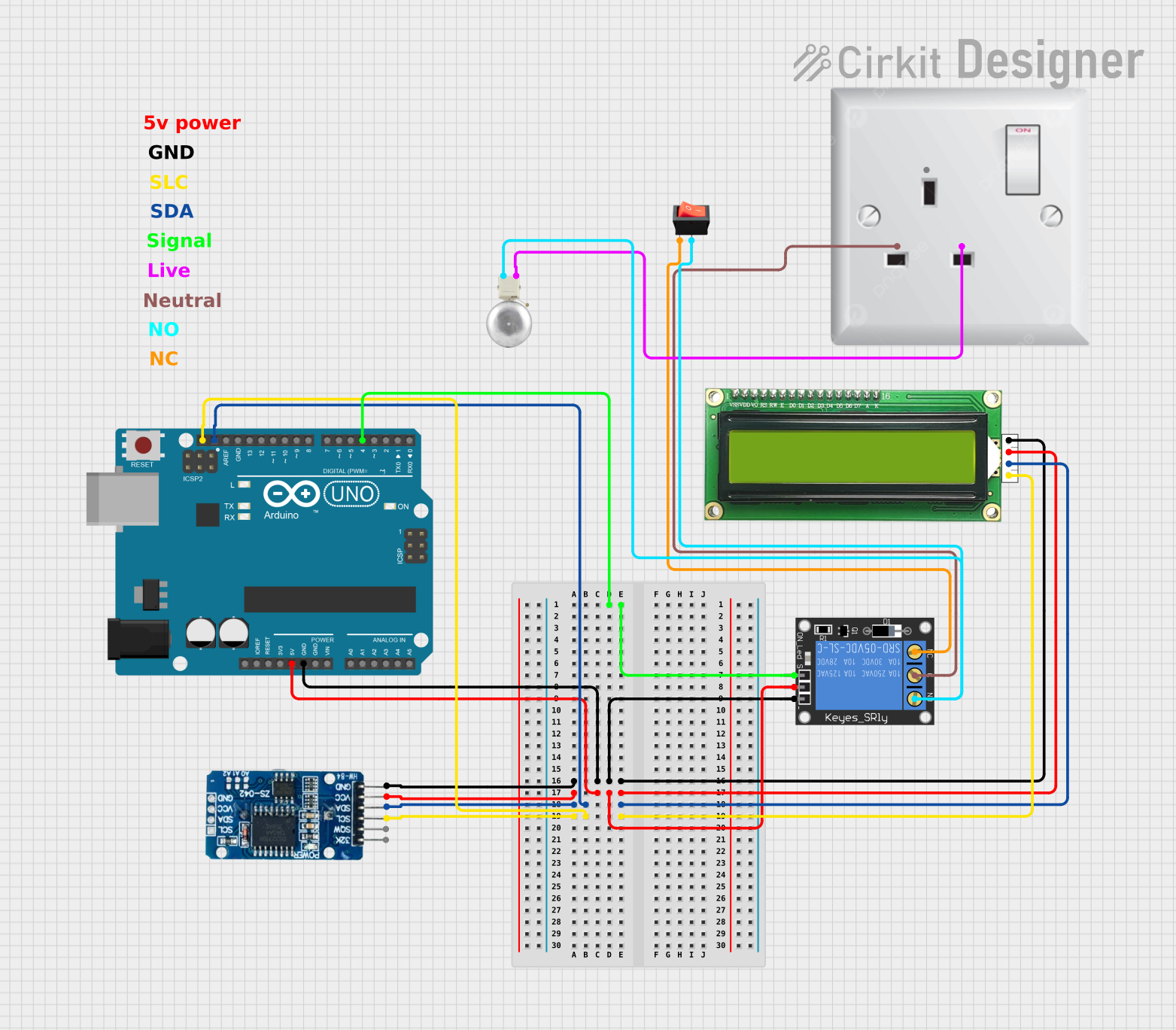
This circuit is designed to interface an Arduino UNO with a 1-Channel Relay, an MKE-M07 LCD1602 I2C display, an RTC DS3231 real-time clock, and a rocker switch to control an AC-powered gong. The Arduino UNO serves as the central microcontroller, managing the interactions between the relay, the display, the real-time clock, and the switch. The relay is used to control the power to the gong, while the LCD and RTC provide a user interface and timekeeping functionality, respectively.
Component List
Arduino UNO
- Microcontroller board based on the ATmega328P
- Provides digital and analog I/O pins
- Powers and communicates with other components in the circuit
1-Channel Relay (5V 10A)
- Electromechanical switch that allows control of a high-power circuit by a low-power signal
- Used to control the AC gong
MKE-M07 LCD1602 I2C
- Alphanumeric liquid crystal display with 16 characters and 2 lines
- Uses I2C communication for displaying information
Rocker Switch
- A simple on/off switch
- Used to manually control the relay
RTC DS3231
- A real-time clock module for timekeeping
- Provides accurate time and date
AC Wall Plug Point
- Provides AC power to the circuit
- Connects to the relay to control the gong
Gong
- An AC-powered device that produces a sound when activated
- Controlled by the relay
Wiring Details
Arduino UNO
D4connected to Relay signal pinGNDconnected to common ground net5Vconnected to common 5V power netSDAconnected to I2C data lineSCLconnected to I2C clock line
1-Channel Relay (5V 10A)
signalconnected to Arduino UNOD4groundconnected to common ground netpowerconnected to common 5V power netNC(Normally Closed) connected to rocker switchinputC(Common) connected to AC wall plug pointNNO(Normally Open) connected to rocker switchoutput
MKE-M07 LCD1602 I2C
GNDconnected to common ground net5Vconnected to common 5V power netSDAconnected to I2C data lineSCLconnected to I2C clock line
Rocker Switch
inputconnected to RelayNCoutputconnected to Gong and RelayNO
RTC DS3231
GNDconnected to common ground netVCCconnected to common 5V power netSDAconnected to I2C data lineSCLconnected to I2C clock line
AC Wall Plug Point
Nconnected to RelayCLconnected to Gong
Gong
- Connected to AC wall plug point
Land rocker switchoutput
Documented Code
Arduino UNO - sketch.ino
void setup() {
  // put your setup code here, to run once:

}

void loop() {
  // put your main code here, to run repeatedly:

}
Arduino UNO - documentation.txt
(No additional documentation provided for the code)
(Note: The actual functionality of the code is not provided in the input, so the code section only includes the template for an Arduino sketch. Additional code would be needed to control the relay, read the time from the RTC, and display information on the LCD.)