
Circuit Documentation
Summary of the Circuit
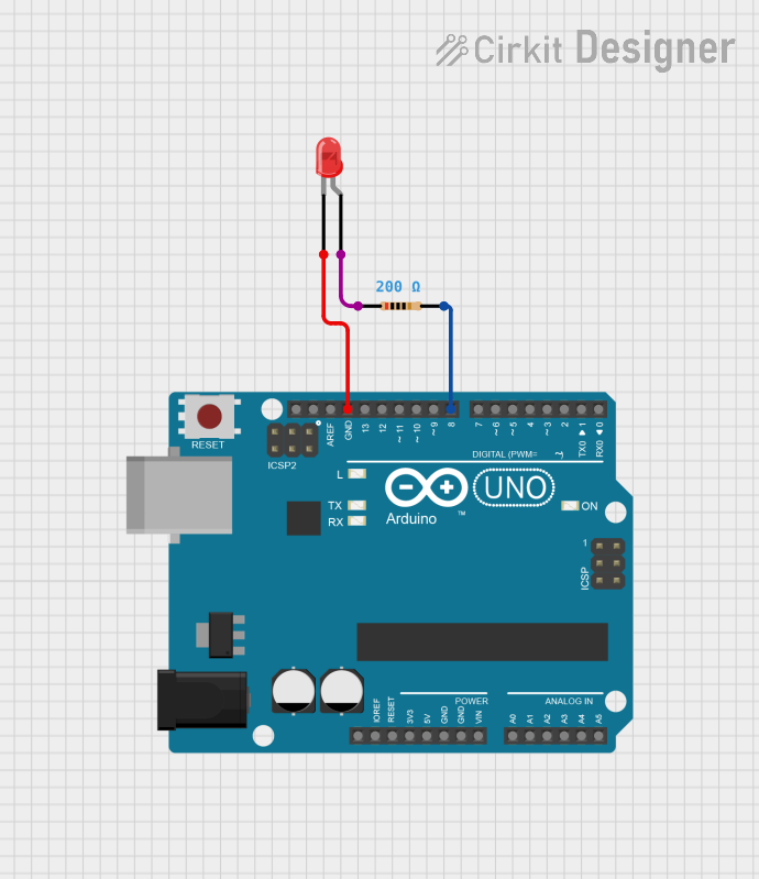
This circuit consists of an Arduino UNO microcontroller, a red two-pin LED, and a resistor. The purpose of the circuit is to illuminate the LED using a digital output from the Arduino UNO. The LED is connected to the Arduino with a series resistor to limit the current and protect the LED from damage. The Arduino's digital pin 8 is configured as an output to control the LED. The ground pin of the Arduino is used to complete the circuit.
Component List
Arduino UNO
- Description: A microcontroller board based on the ATmega328P.
- Pins Used: GND, D8
- Purpose: Acts as the control unit for the LED, providing power and signal.
LED: Two Pin (red)
- Description: A basic red light-emitting diode.
- Pins Used: cathode, anode
- Purpose: Emits light when powered.
Resistor
- Description: A passive two-terminal electrical component that implements electrical resistance as a circuit element.
- Value: 200 Ohms
- Pins Used: pin1, pin2
- Purpose: Limits the current flowing through the LED to prevent damage.
Wiring Details
Arduino UNO
- GND is connected to the cathode of the LED.
- D8 is connected to pin2 of the Resistor.
LED: Two Pin (red)
- Cathode is connected to the GND of the Arduino UNO.
- Anode is connected to pin1 of the Resistor.
Resistor
- Pin1 is connected to the anode of the LED.
- Pin2 is connected to D8 of the Arduino UNO.
Documented Code
Arduino UNO Code (sketch.ino)
void setup() {
  pinMode(8, OUTPUT); // Set digital pin 8 as an output
}

void loop() {
  // Main code to run repeatedly:
  digitalWrite(8, HIGH); // Turn on the LED connected to pin 8
}
File Name: sketch.ino
Description: This code configures pin 8 of the Arduino UNO as an output and then continuously sets it to HIGH, which turns on the connected LED. The loop function runs indefinitely, keeping the LED illuminated.