
Arduino Uno Smoke Detector with I2C Display and Buzzer Alert
View and Edit Project In Cirkit Designer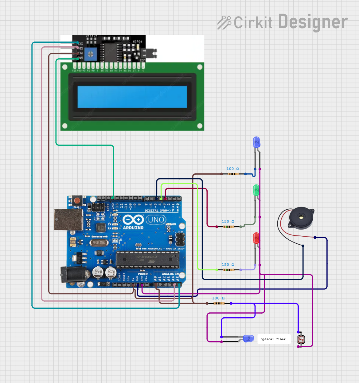
Circuit Documentation
Summary
This circuit is a smoke detection system using an Arduino Uno R3 microcontroller. It includes an I2C display for visual feedback, multiple LEDs for status indication, a buzzer for audible alerts, and a photocell (LDR) for smoke detection. The system reads the LDR value to detect smoke and adjusts the reference voltage using two switches. When smoke is detected, the system activates the red LED and buzzer, and displays a message on the I2C display.
Component List
Arduino Uno R3
- Description: Microcontroller board based on the ATmega328P.
- Pins: D8, D9, D10, D11, D12, D13, GND, AREF, SDA, SCL, D0/RX, D1/Tx, D2, D3, D4, D5, D6, D7, A5/SCL, A4/SDA, A3, A2, A1, A0, Vin, 5V, 3.3V, RESET, IOREF, NONE, USB Jack, Power Jack.
LED: Two Pin (green)
- Description: Green LED.
- Pins: cathode, anode.
LED: Two Pin (blue)
- Description: Blue LED.
- Pins: cathode, anode.
LED: Two Pin (red)
- Description: Red LED.
- Pins: cathode, anode.
Buzzer
- Description: Buzzer for audible alerts.
- Pins: GND, IN.
Photocell (LDR)
- Description: Light-dependent resistor for smoke detection.
- Pins: pin 0, pin 1.
Resistor (100 Ohms)
- Description: Resistor with 100 Ohms resistance.
- Pins: pin1, pin2.
Resistor (150 Ohms)
- Description: Resistor with 150 Ohms resistance.
- Pins: pin1, pin2.
I2C DISPLAY
- Description: I2C display for visual feedback.
- Pins: GND, VCC, SDL, SCL.
Wiring Details
Arduino Uno R3
- GND connected to GND of I2C DISPLAY.
- D3 connected to pin1 of Resistor (150 Ohms).
- D4 connected to pin1 of Resistor (150 Ohms).
- D5 connected to GND of Buzzer.
- A5/SCL connected to SCL of I2C DISPLAY.
- A4/SDA connected to SDL of I2C DISPLAY.
- A0 connected to 5V of Arduino Uno R3, pin1 of Resistor (100 Ohms), VCC of I2C DISPLAY, and pin1 of Resistor (100 Ohms).
LED: Two Pin (green)
- anode connected to GND of Arduino Uno R3.
- cathode connected to pin2 of Resistor (150 Ohms).
LED: Two Pin (blue)
- anode connected to GND of Arduino Uno R3.
- cathode connected to pin2 of Resistor (100 Ohms).
LED: Two Pin (red)
- anode connected to GND of Arduino Uno R3.
- cathode connected to pin2 of Resistor (150 Ohms).
Buzzer
- GND connected to D5 of Arduino Uno R3.
- IN connected to GND of Arduino Uno R3.
Photocell (LDR)
- pin 0 connected to cathode of LED: Two Pin (blue) and pin2 of Resistor (100 Ohms).
- pin 1 connected to anode of LED: Two Pin (blue), anode of LED: Two Pin (red), anode of LED: Two Pin (blue), and anode of LED: Two Pin (green).
Resistor (100 Ohms)
- pin1 connected to A0 of Arduino Uno R3.
- pin2 connected to cathode of LED: Two Pin (blue).
Resistor (150 Ohms)
- pin1 connected to D3 of Arduino Uno R3.
- pin2 connected to cathode of LED: Two Pin (green).
Resistor (150 Ohms)
- pin1 connected to D4 of Arduino Uno R3.
- pin2 connected to cathode of LED: Two Pin (red).
I2C DISPLAY
- GND connected to GND of Arduino Uno R3.
- VCC connected to A0 of Arduino Uno R3.
- SDL connected to A4/SDA of Arduino Uno R3.
- SCL connected to A5/SCL of Arduino Uno R3.
Documented Code
#include <LiquidCrystal_I2C_Hangul.h> // Include the library for the display

LiquidCrystal_I2C_Hangul lcd(0x27, 16, 2); // Set the LCD address to 0x27 for a 16 chars and 2 line display

const int ldrPin = A0;     // LDR connected to A0
const int blueLEDPin = 13; // Internal LED for blinking
const int greenLEDPin = 3; // Green LED connected to D3
const int redLEDPin = 4;   // Red LED connected to D4
const int buzzerPin = 5;   // Buzzer connected to D5
const int switch1Pin = 6;  // Switch 1 connected to D6
const int switch2Pin = 7;  // Switch 2 connected to D7

int referenceVoltage = 860; // Initial reference voltage (adjustable)
int ldrValue = 0;

void setup() {
  pinMode(blueLEDPin, OUTPUT);
  pinMode(greenLEDPin, OUTPUT);
  pinMode(redLEDPin, OUTPUT);
  pinMode(buzzerPin, OUTPUT);
  pinMode(switch1Pin, INPUT_PULLUP);
  pinMode(switch2Pin, INPUT_PULLUP);

  lcd.init(); // initialize the lcd
  lcd.begin(16, 2); // Corrected to include the number of columns and rows
  lcd.clear();                 // clear display
  lcd.setCursor(0, 0);         // move cursor to   (0, 0)
  lcd.print("Hello, This is a");
  lcd.setCursor(0, 1);
  lcd.print("Optical Sensor");
  delay(2000);
  lcd.clear();
  lcd.setCursor(0, 0);
  lcd.print("Smoke Detector");
  lcd.setCursor(0, 1);
  lcd.print("System");
  delay(2000);
  lcd.clear();

  Serial.begin(9600);
}

void loop() {
  // Blink the blue LED
  digitalWrite(blueLEDPin, HIGH);
  delay(500);
  digitalWrite(blueLEDPin, LOW);
  delay(500);

  // Read the LDR value
  ldrValue = analogRead(ldrPin);
  Serial.println(ldrValue);

  // Adjust reference voltage using switches
  if (digitalRead(switch1Pin) == LOW) {
    referenceVoltage += 5;
    delay(100);
  }
  if (digitalRead(switch2Pin) == LOW) {
    referenceVoltage -= 5;
    delay(100);
  }

  // Check if smoke is detected
  if (ldrValue > referenceVoltage) {
    // Smoke detected
    digitalWrite(greenLEDPin, LOW);
    digitalWrite(redLEDPin, HIGH);
    digitalWrite(buzzerPin, HIGH);

    lcd.clear();
    lcd.setCursor(0, 0);
    lcd.print("Smoke Detected");
    lcd.setCursor(0, 1);
    lcd.print(ldrValue);
    delay(2000);
  } else {
    // No smoke detected
    digitalWrite(greenLEDPin, HIGH);
    digitalWrite(redLEDPin, LOW);
    digitalWrite(buzzerPin, LOW);

    lcd.clear();
    lcd.setCursor(0, 0);
    lcd.print("No Smoke Detected");
    lcd.setCursor(0, 1);
    lcd.print(ldrValue);
    delay(2000);
  }

  delay(200); // Short delay to avoid rapid switching
}
This code initializes the components, reads the LDR value, and adjusts the reference voltage using two switches. It then checks if smoke is detected and updates the LEDs, buzzer, and I2C display accordingly.