Multi-Functional Robotic Control System with Sensor Integration and Display Interface
Circuit Documentation
Summary
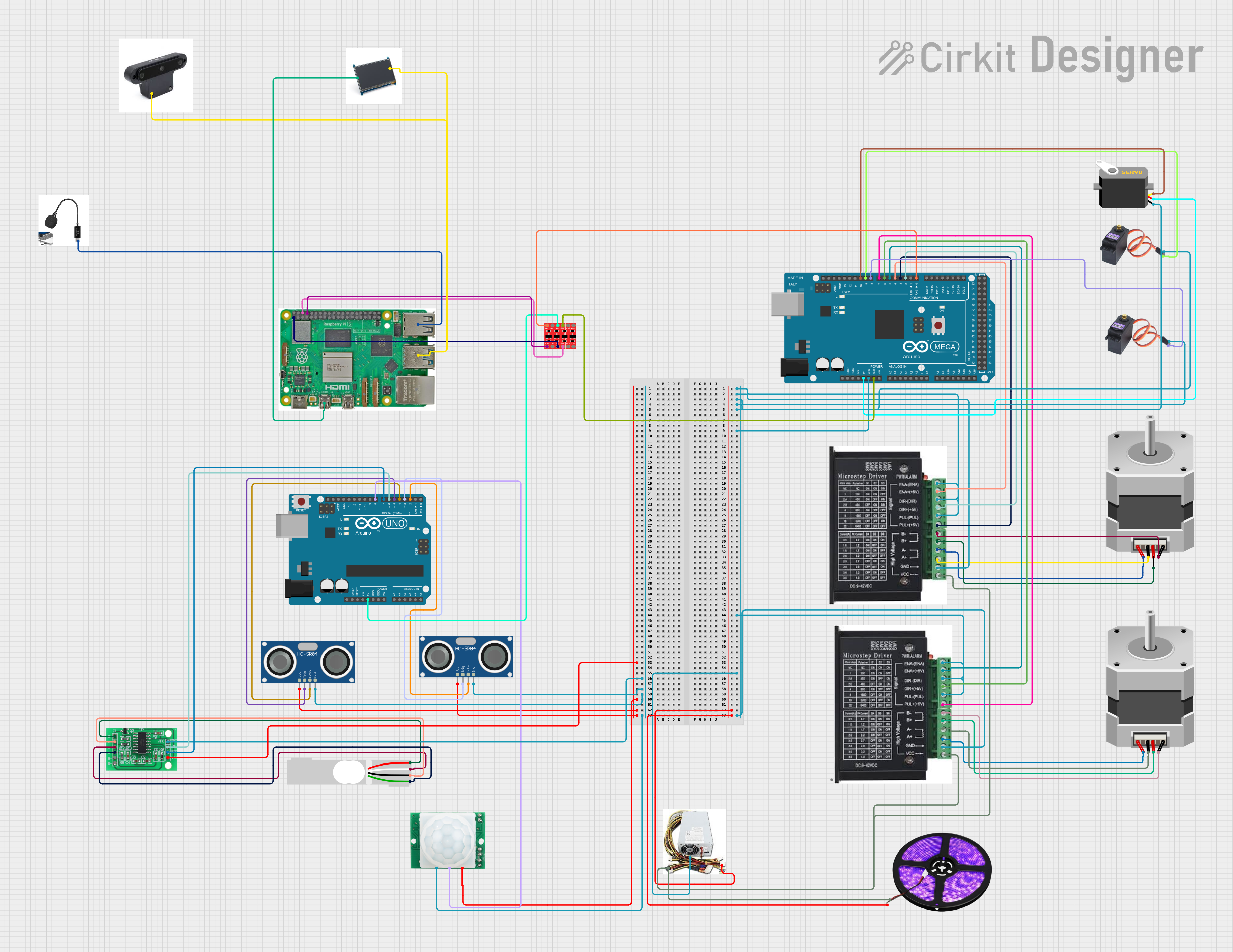
This document provides a detailed overview of a complex circuit that integrates various components including microcontrollers (Arduino Mega 2560 and Arduino UNO), stepper motors, servo motors, sensors (HC-SR04 Ultrasonic, HC-SR501 Motion, Load Cell), drivers, a Raspberry Pi 5, and other peripherals. The circuit is designed to perform multiple functions, which may include motion detection, distance measurement, weight sensing, and motor control. The microcontrollers are programmed to manage the inputs and outputs of the circuit, interfacing with the sensors and actuators to perform the desired tasks.
Component List
Microcontrollers
- Arduino Mega 2560: A microcontroller board based on the ATmega2560, with a wide range of input/output pins.
- Arduino UNO: A microcontroller board based on the ATmega328P, commonly used for beginners and simple projects.
Motors and Drivers
- Stepper Motor (Bipolar): A type of motor that is driven by electric pulses and capable of precise position control.
- MG996R: A high-torque digital servo motor commonly used in robotics.
- Servo: A rotary actuator that allows for precise control of angular position.
- Stepper Driver: A device that controls the operation of a stepper motor.
Sensors
- HC-SR04 Ultrasonic Sensor: A sensor that measures distance by emitting ultrasonic waves and measuring the time taken for the echo to return.
- HC-SR501 Motion Sensor: A passive infrared sensor that detects motion by measuring changes in the infrared levels emitted by surrounding objects.
- Load Cell - Red/white/black/green: A transducer that converts force into an electrical signal, used for weight measurement.
- HX711 - Bridge Sensor Interface: An ADC converter that allows for high-precision reading of load cells.
Power Supply and Conversion
- Power Supply: Provides regulated voltage for the circuit.
- Bi-Directional Logic Level Converter: A device that safely steps down 5V signals to 3.3V and steps up 3.3V to 5V at the same time.
Output Devices
- LED Light Strips (Violet): Strips of LEDs that emit violet light, used for illumination or indication.
- LCD: A liquid crystal display used for visual output.
Other Components
- Raspberry Pi 5: A small single-board computer with a broad set of capabilities.
- HC-SR04 Ultrasonic Sensor: A sensor used for measuring distances via ultrasonic sound waves.
- HC-SR501 Motion Sensor: A sensor that detects motion based on infrared signals.
- Microphone: An acoustic-to-electric transducer or sensor that converts sound into an electrical signal.
- OAK-D: An AI and computer vision development platform.
Wiring Details
Arduino Mega 2560
- GND: Connected to the ground pins of MG996R servos, stepper drivers, and the servo.
- 5V: Powers the Servo.
- D0 RX0: Connected to HV1 on the Bi-Directional Logic Level Converter.
- D2 PWM: Connected to DIR+ on the first stepper driver.
- D3 PWM: Connected to PUL + on the first stepper driver.
- D4 PWM: Connected to ENA - on the first stepper driver.
- D5 PWM: Connected to ENA - on the second stepper driver.
- D6 PWM: Connected to DIR+ on the second stepper driver.
- D7 PWM: Connected to PUL + on the second stepper driver.
- D8 PWM: Connected to SIG on the first MG996R servo.
- D9 PWM: Connected to SIG on the second MG996R servo.
- D10 PWM: Connected to the pulse pin on the Servo.
Arduino UNO
- 5V: Powers the Bi-Directional Logic Level Converter.
- D8: Connected to OUT on the HC-SR501 Motion Sensor.
- D7: Connected to SCK - CLOCK (IN) on the HX711 Bridge Sensor Interface.
- D6: Connected to DATA (OUT) on the HX711 Bridge Sensor Interface.
- D5: Connected to TRIG on the first HC-SR04 Ultrasonic Sensor.
- D4: Connected to ECHO on the first HC-SR04 Ultrasonic Sensor.
- D3: Connected to TRIG on the second HC-SR04 Ultrasonic Sensor.
- D2: Connected to ECHO on the second HC-SR04 Ultrasonic Sensor.
Stepper Motors
- Connected to the corresponding A+, A-, B+, and B- pins on the stepper drivers.
Power Supply
- 12V: Powers the stepper drivers and LED Light Strips.
- GND: Common ground for the circuit.
Raspberry Pi 5
- Micro HDMI 1: Connected to HDMI on the LCD.
- USB 3.0: Connected to USB on the LCD and OAK-D.
- USB 2.0: Connected to USB on the Microphone.
- GND: Connected to GND on the Bi-Directional Logic Level Converter.
- 3.3v: Powers the Bi-Directional Logic Level Converter.
- GPIO 14: Connected to LV1 on the Bi-Directional Logic Level Converter.
Load Cell and HX711
- E+, A-, E-, A+: Load Cell connected to the corresponding pins on the HX711.
Documented Code
Arduino Mega 2560 Code (sketch.ino)
void setup() {
  // put your setup code here, to run once:

}

void loop() {
  // put your main code here, to run repeatedly:

}
Arduino UNO Code (sketch.ino)
void setup() {
  // put your setup code here, to run once:

}

void loop() {
  // put your main code here, to run repeatedly:

}
Note: The actual functionality of the code is not provided in the input and would need to be implemented based on the specific requirements of the circuit.