Arduino Leonardo-Based Motion Detection and Distance Measurement System
Circuit Documentation
Summary
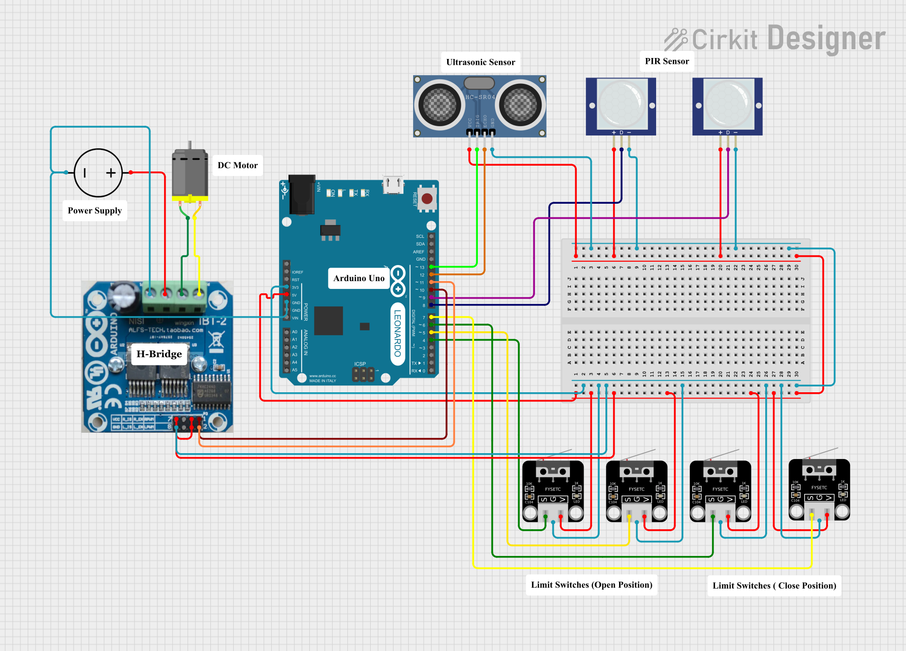
The circuit in question is designed to interface an Arduino Leonardo with various sensors and a motor driver to control a DC motor. The sensors include PIR motion sensors, limit switches, and an HC-SR04 ultrasonic distance sensor. The Arduino Leonardo is responsible for processing the inputs from these sensors and controlling the motor driver, which in turn controls the DC motor. The circuit is powered by a DC power source.
Component List
Arduino Leonardo (Rev3b)
- Microcontroller board based on the ATmega32u4
- Features digital I/O pins, analog input pins, and PWM pins
- Provides 3.3V and 5V output for powering sensors and other components
PIR Motion Sensor (Wokwi Compatible)
- Passive Infrared sensor for detecting motion
- Outputs a digital signal when motion is detected
Limit Switch
- Mechanical switch that is actuated by the physical movement of an object
- Commonly used to detect the presence or position of objects in industrial control applications
IBT-2 H-Bridge Motor Driver
- Motor driver module capable of driving high current loads
- Uses an H-Bridge configuration for controlling the direction and speed of a DC motor
DC Motor
- A simple electric motor that runs on direct current (DC) power
- Typically used for driving mechanical loads
HC-SR04 Ultrasonic Distance Sensor (Wokwi Compatible)
- Ultrasonic ranging module for distance measurement
- Operates by sending an ultrasonic pulse and measuring the time taken for the echo to return
DC Power Source
- Provides the necessary power to the circuit
- Typically includes a positive and a ground terminal
Wiring Details
Arduino Leonardo (Rev3b)
D4/A6connected to Limit Switch signal pinD5 PWMconnected to another Limit Switch signal pinD6 PWM/A7connected to another Limit Switch signal pinD7connected to another Limit Switch signal pin3V3connected to the ground pins of all Limit Switches, PIR Motion Sensors, HC-SR04, and IBT-2 H-Bridge Motor Driver5Vconnected to the voltage pins of all Limit Switches, PIR Motion Sensors, HC-SR04, and IBT-2 H-Bridge Motor DriverGNDconnected to the DC Power Source groundD8/A8connected to PIR Motion Sensor OUT pinD9 PWM/A9connected to another PIR Motion Sensor OUT pinD10 PWM/A10connected to IBT-2 H-Bridge Motor Driver RPWM pinD11 PWMconnected to IBT-2 H-Bridge Motor Driver LPWM pinD12/A11connected to HC-SR04 ECHO pinD13 PWMconnected to HC-SR04 TRIG pin
PIR Motion Sensor (Wokwi Compatible)
VCCconnected to 5V from Arduino LeonardoOUTconnected toD8/A8orD9 PWM/A9on Arduino LeonardoGNDconnected to common ground
Limit Switch
Sconnected toD4/A6,D5 PWM,D6 PWM/A7, orD7on Arduino LeonardoGconnected to common groundVconnected to 5V from Arduino Leonardo
IBT-2 H-Bridge Motor Driver
VCCconnected to 5V from Arduino LeonardoGNDconnected to common groundL_ENandR_ENconnected to 5V from Arduino LeonardoRPWMconnected toD10 PWM/A10on Arduino LeonardoLPWMconnected toD11 PWMon Arduino Leonardo- Motor connections to DC Motor pins
DC Motor
pin 1andpin 2connected to IBT-2 H-Bridge Motor Driver
HC-SR04 Ultrasonic Distance Sensor (Wokwi Compatible)
VCCconnected to 5V from Arduino LeonardoTRIGconnected toD13 PWMon Arduino LeonardoECHOconnected toD12/A11on Arduino LeonardoGNDconnected to common ground
DC Power Source
Groundconnected to common groundPositiveconnected to IBT-2 H-Bridge Motor Driver
Documented Code
There is no code provided for the microcontroller. The code would typically include initialization of the input/output pins, reading sensor states, implementing control logic for the motor based on sensor inputs, and handling timing for the ultrasonic sensor measurements. Without the code, the specific functionality and behavior of the circuit cannot be documented further.