
Battery-Powered Stepper Motor Control System with STM32 and A4988 Drivers
View and Edit Project In Cirkit Designer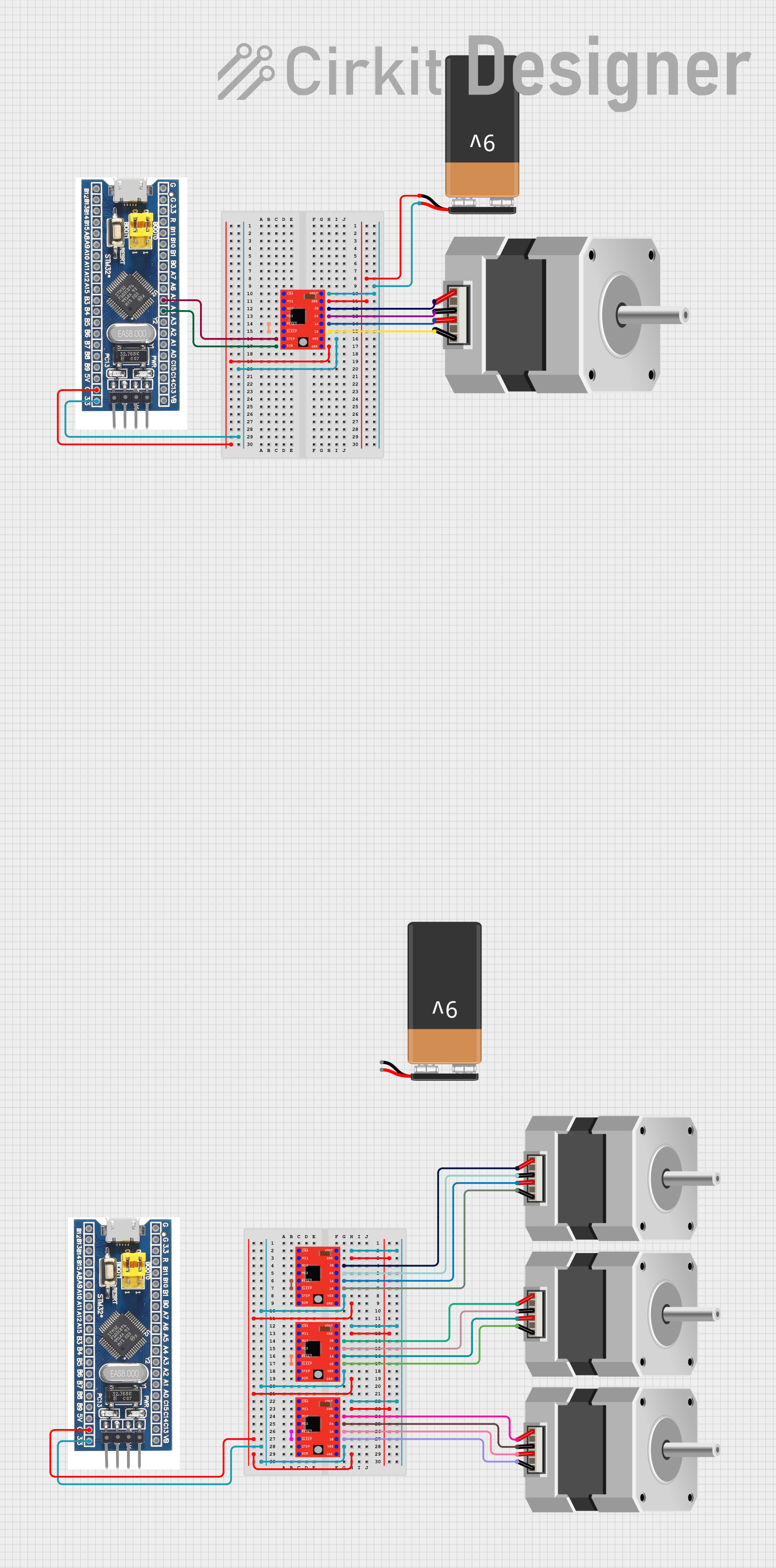
Circuit Documentation
Summary
This circuit involves the use of multiple stepper motors controlled by A4988 stepper motor drivers, which are in turn managed by STM32F103C8T6 microcontrollers. The circuit is powered by 9V batteries. The primary purpose of this setup is to control the stepper motors using the microcontrollers, with the A4988 drivers acting as intermediaries to handle the power and control signals required by the motors.
Component List
STM32F103C8T6 Microcontroller
- Description: A 32-bit ARM Cortex-M3 microcontroller.
- Pins: GND, 3.3V, reset, B11, B10, B1, B0, A7, A6, A5, A4, A3, A2, A1, A0, C15, C14, C13, VBT, 3.3, 5V, B12, B13, b14, B15, A8, A9, A10, A11, A12, A15, B3, B4, B5, B6, B7, B8, B9, SWIO, SWCLK
Stepper Motor (Bipolar)
- Description: A bipolar stepper motor.
- Pins: D, B, C, A
A4988 Stepper Motor Driver (Red)
- Description: A microstepping driver for controlling bipolar stepper motors.
- Pins: ENABLE, MS1, MS2, MS3, RESET, SLEEP, STEP, DIR, VMOT, GND, 2B, 2A, 1A, 1B, VDD
NEMA23 Stepper Motor
- Description: A high-torque stepper motor.
- Pins: D, B, C, A
9V Battery
- Description: A standard 9V battery for powering the circuit.
- Pins: -, +
Wiring Details
STM32F103C8T6 Microcontroller
- A5 connected to STEP of A4988 Stepper Motor Driver (Red)
- A4 connected to DIR of A4988 Stepper Motor Driver (Red)
- 3.3 connected to VDD of A4988 Stepper Motor Driver (Red)
- GND connected to GND of A4988 Stepper Motor Driver (Red)
Stepper Motor (Bipolar)
- A connected to 2B of A4988 Stepper Motor Driver (Red)
- C connected to 2A of A4988 Stepper Motor Driver (Red)
- B connected to 1A of A4988 Stepper Motor Driver (Red)
- D connected to 1B of A4988 Stepper Motor Driver (Red)
A4988 Stepper Motor Driver (Red)
- VMOT connected to + of 9V Battery
- GND connected to - of 9V Battery
- RESET connected to SLEEP of A4988 Stepper Motor Driver (Red)
- 2B connected to A of NEMA23 Stepper Motor
- 2A connected to C of NEMA23 Stepper Motor
- 1A connected to B of NEMA23 Stepper Motor
- 1B connected to D of NEMA23 Stepper Motor
- STEP connected to A5 of STM32F103C8T6
- DIR connected to A4 of STM32F103C8T6
- VDD connected to 3.3 of STM32F103C8T6
- GND connected to GND of STM32F103C8T6
NEMA23 Stepper Motor
- A connected to 2B of A4988 Stepper Motor Driver (Red)
- C connected to 2A of A4988 Stepper Motor Driver (Red)
- B connected to 1A of A4988 Stepper Motor Driver (Red)
- D connected to 1B of A4988 Stepper Motor Driver (Red)
9V Battery
- + connected to VMOT of A4988 Stepper Motor Driver (Red)
- - connected to GND of A4988 Stepper Motor Driver (Red)
Code
There is no code provided for the microcontrollers in this circuit.
This documentation provides a comprehensive overview of the circuit, including a summary, detailed component list, wiring details, and code (if any). This should help in understanding the design and functionality of the circuit.