
Circuit Documentation
Summary
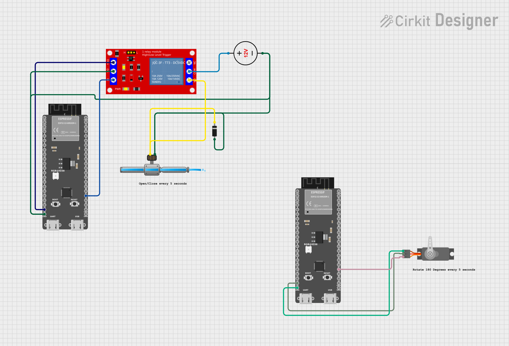
This circuit is designed to control a solenoid irrigation valve and a servo motor using an ESP32-S3 microcontroller. The solenoid valve is operated through a relay module, which is controlled by the ESP32-S3. The servo motor is also controlled via PWM signals from the ESP32-S3. The circuit is powered by a 12V DC power supply, and the ESP32-S3 is powered through a 5V connection.
Component List
1. ESP32-S3 (beta)
- Description: A powerful microcontroller with integrated Wi-Fi and Bluetooth capabilities.
- Purpose: Controls the relay module for the solenoid valve and the servo motor.
2. Solenoid Irrigation Valve
- Description: An electromechanical valve for controlling the flow of water.
- Purpose: Opens and closes to allow or stop water flow for irrigation.
3. 1 Channel 5V Relay Module
- Description: A relay module that allows a low-power signal to control a high-power device.
- Purpose: Acts as a switch to control the solenoid valve.
4. Diode
- Description: A semiconductor device that allows current to flow in one direction only.
- Purpose: Protects the circuit from back EMF generated by the solenoid valve.
5. 12V DC Power Supply
- Description: A power supply that provides 12V DC voltage.
- Purpose: Powers the solenoid valve and relay module.
6. Servo
- Description: A rotary actuator that allows for precise control of angular position.
- Purpose: Used for applications requiring controlled movement.
Wiring Details
ESP32-S3 (beta)
- 5V: Connected to the VCC+ pin of the 1 Channel 5V Relay Module.
- GND: Connected to the GND pin of the 1 Channel 5V Relay Module and the GND pin of the Servo.
- 21: Connected to the IN pin of the 1 Channel 5V Relay Module and the PWM pin of the Servo.
Solenoid Irrigation Valve
- Positive: Connected to the N.O. pin of the 1 Channel 5V Relay Module.
- Negative: Connected to the GND pin of the 12V DC Power Supply and the GND pin of the 1 Channel 5V Relay Module.
1 Channel 5V Relay Module
- VCC+: Connected to the 5V pin of the ESP32-S3.
- VCC- (GND): Connected to the GND pin of the ESP32-S3 and the Negative pin of the Solenoid Irrigation Valve.
- IN: Connected to the GPIO 21 pin of the ESP32-S3.
- N.O.: Connected to the Positive pin of the Solenoid Irrigation Valve.
- COM: Connected to the Positive pin of the 12V DC Power Supply.
Diode
- Anode: Connected to the N.O. pin of the 1 Channel 5V Relay Module.
- Cathode: Connected to the Positive pin of the Solenoid Irrigation Valve.
12V DC Power Supply
- Positive: Connected to the COM pin of the 1 Channel 5V Relay Module.
- Negative: Connected to the Negative pin of the Solenoid Irrigation Valve.
Servo
- VCC: Connected to the 5V pin of the ESP32-S3.
- GND: Connected to the GND pin of the ESP32-S3.
- PWM: Connected to the GPIO 21 pin of the ESP32-S3.
Documented Code
ESP32-S3 Code for Solenoid Control
/*
 * Arduino Sketch for controlling a solenoid valve using an ESP32-S3 and a relay.
 * The solenoid valve is opened and closed every 5 seconds. The ESP32-S3 controls
 * the relay module, which in turn controls the solenoid valve. The relay is
 * connected to GPIO 21 of the ESP32-S3.
 */

const int relayPin = 21; // GPIO pin connected to the relay module

void setup() {
  // Initialize the relay pin as an output
  pinMode(relayPin, OUTPUT);
  // Start with the relay off
  digitalWrite(relayPin, LOW);
}

void loop() {
  // Turn the relay on (close the solenoid valve)
  digitalWrite(relayPin, HIGH);
  delay(5000); // Wait for 5 seconds

  // Turn the relay off (open the solenoid valve)
  digitalWrite(relayPin, LOW);
  delay(5000); // Wait for 5 seconds
}
ESP32-S3 Code for Servo Control
/*
 * Arduino Sketch for controlling a servo motor using an ESP32-S3.
 * The servo motor is smoothly rotated from 0 to 180 degrees every 5 seconds.
 * The ESP32-S3 controls the servo motor via PWM on GPIO 21.
 */

#include <ESP32Servo.h>

const int servoPin = 21; // GPIO pin connected to the servo PWM
Servo myServo;           // Create a Servo object

void setup() {
  // Attach the servo on the specified pin
  myServo.attach(servoPin);
}

void loop() {
  // Rotate the servo from 0 to 180 degrees
  for (int pos = 0; pos <= 180; pos++) {
    myServo.write(pos);  // Set the servo position
    delay(28);           // Delay for smooth movement
  }

  // Rotate the servo from 180 to 0 degrees
  for (int pos = 180; pos >= 0; pos--) {
    myServo.write(pos);  // Set the servo position
    delay(28);           // Delay for smooth movement
  }
}
This documentation provides a comprehensive overview of the circuit, detailing each component, its purpose, wiring connections, and the code used for operation.