
Battery-Powered Servo Control System with 2S 30A BMS and TP5100 Charger
View and Edit Project In Cirkit Designer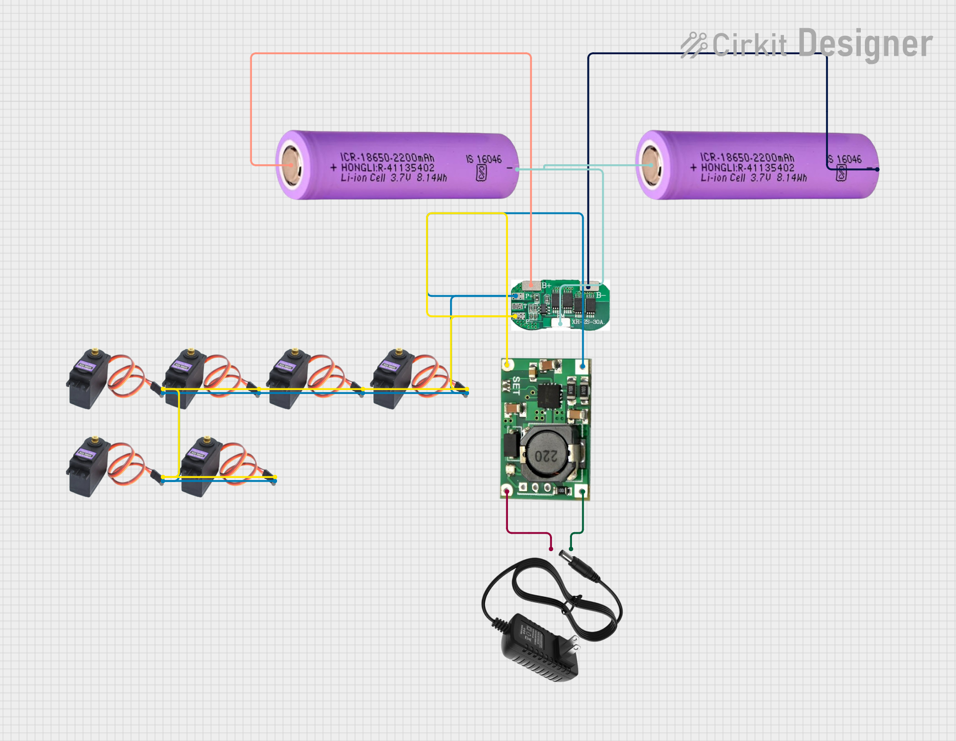
Circuit Documentation
Summary
This document provides a detailed overview of a circuit designed to manage and control a battery system with multiple servos. The circuit includes a Battery Management System (BMS), a TP5100 charging module, a 12V power supply, and several MG996R servos. The BMS ensures safe operation of the batteries, while the TP5100 module handles charging. The servos are powered and controlled through the BMS and TP5100 module.
Component List
2S 30A BMS
- Description: Battery Management System for 2S Li-ion batteries.
- Pins: B+, B-, BM, P-, T, P+
TP5100
- Description: Charging module for Li-ion batteries.
- Pins: B-, B+, IN-, IN+
12V Power Supply
- Description: Provides 12V DC power.
- Pins: +, -
Battery 18650
- Description: 3.7V Li-ion battery.
- Pins: +, -
MG996R
- Description: High-torque servo motor.
- Pins: GND, VCC, SIG
Wiring Details
2S 30A BMS
- B+: Connected to the positive terminal of the first Battery 18650.
- B-: Connected to the negative terminal of the second Battery 18650.
- BM: Connected between the positive terminal of the second Battery 18650 and the negative terminal of the first Battery 18650.
- P-: Connected to the GND pins of all MG996R servos and the B- pin of the TP5100.
- P+: Connected to the VCC pins of all MG996R servos and the B+ pin of the TP5100.
TP5100
- B-: Connected to the P- pin of the 2S 30A BMS.
- B+: Connected to the P+ pin of the 2S 30A BMS.
- IN-: Connected to the negative terminal of the 12V power supply.
- IN+: Connected to the positive terminal of the 12V power supply.
12V Power Supply
- -: Connected to the IN- pin of the TP5100.
- +: Connected to the IN+ pin of the TP5100.
Battery 18650 (First Battery)
- +: Connected to the B+ pin of the 2S 30A BMS.
- -: Connected to the BM pin of the 2S 30A BMS and the positive terminal of the second Battery 18650.
Battery 18650 (Second Battery)
- +: Connected to the BM pin of the 2S 30A BMS and the negative terminal of the first Battery 18650.
- -: Connected to the B- pin of the 2S 30A BMS.
MG996R Servos
- GND: Connected to the P- pin of the 2S 30A BMS.
- VCC: Connected to the P+ pin of the 2S 30A BMS.
- SIG: Not connected in this documentation.
Documented Code
There is no code provided for the microcontrollers in this circuit.
This documentation provides a comprehensive overview of the components and their connections within the circuit. Each component is described, and detailed wiring instructions are provided to ensure correct assembly and operation.