
ESP32 and L298N Motor Driver-Based Wi-Fi Controlled Robotic Vehicle with GPS and Metal Detection
View and Edit Project In Cirkit Designer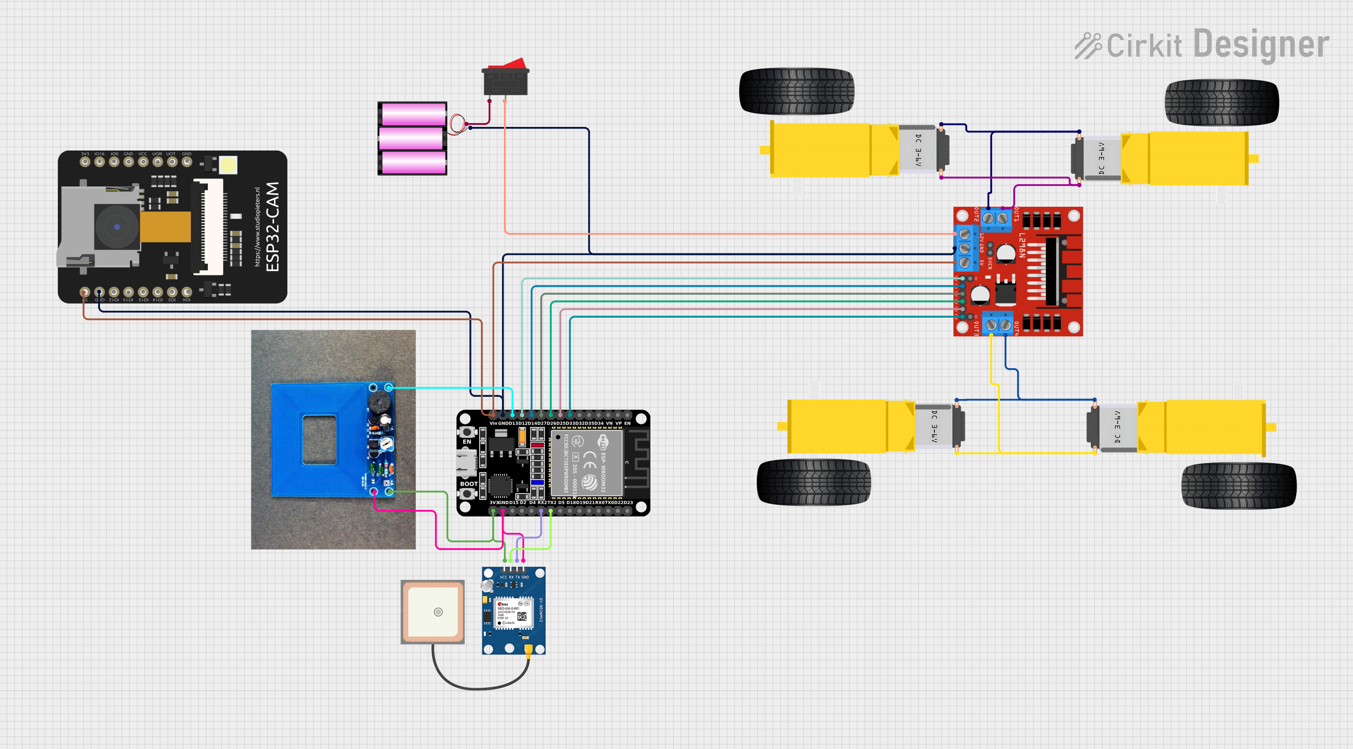
Circuit Documentation
Summary
This document provides a detailed overview of a circuit designed to control a set of gearmotors using an L298N DC motor driver, an ESP32 microcontroller, and various other components including a GPS module, a metal detector, and a rocker switch. The circuit is powered by a 12V battery and includes connections for both power and signal lines.
Component List
Gearmotor DC Wheels Right
- Pins: PIN1, PIN2
- Description: DC motor for the right wheels of the vehicle.
Gearmotor DC Wheels Left
- Pins: PIN1, PIN2
- Description: DC motor for the left wheels of the vehicle.
L298N DC Motor Driver
- Pins: OUT1, OUT2, 12V, GND, 5V, OUT3, OUT4, 5V-ENA-JMP-I, 5V-ENA-JMP-O, +5V-J1, +5V-J2, ENA, IN1, IN2, IN3, IN4, ENB
- Description: Motor driver to control the gearmotors.
GPS NEO 6M
- Pins: VCC, RX, TX, GND
- Description: GPS module for location tracking.
Battery 12V
- Pins: +, -
- Description: Power source for the circuit.
Rocker Switch
- Pins: 1, 2
- Description: Switch to control the power supply.
Metal Detector
- Pins: VCC, GND, D
- Description: Metal detection sensor.
ESP32 CAM
- Pins: 5V, GND, GPIO12, GPIO13, GPIO15, GPIO14, GPIO2, GPIO4, 3.3V, GPIO16, GPIO0, 3.3V / 5V / P_OUT, GPIO3 / RX, GPIO1 / TX
- Description: Camera module with ESP32 microcontroller.
ESP32 (30 pin)
- Pins: EN, VP, VN, D34, D35, D32, D33, D25, D26, D27, D14, D12, D13, GND, Vin, D23, D22, TX0, RX0, D21, D19, D18, D5, TX2, RX2, D4, D2, D15, 3V3
- Description: Main microcontroller for the circuit.
Wiring Details
Gearmotor DC Wheels Right
- PIN1 connected to L298N DC Motor Driver OUT3
- PIN2 connected to L298N DC Motor Driver OUT4
Gearmotor DC Wheels Left
- PIN1 connected to L298N DC Motor Driver OUT4
- PIN2 connected to L298N DC Motor Driver OUT3
L298N DC Motor Driver
- ENB connected to ESP32 (30 pin) D33
- IN4 connected to ESP32 (30 pin) D25
- IN3 connected to ESP32 (30 pin) D26
- IN2 connected to ESP32 (30 pin) D27
- IN1 connected to ESP32 (30 pin) D14
- ENA connected to ESP32 (30 pin) D12
- GND connected to Battery 12V -, ESP32 (30 pin) GND, ESP32 CAM GND
- 5V connected to ESP32 (30 pin) Vin, ESP32 CAM 5V
- 12V connected to Rocker Switch 2
- OUT3 connected to Gearmotor DC Wheels Right PIN1, Gearmotor DC Wheels Left PIN2
- OUT4 connected to Gearmotor DC Wheels Right PIN2, Gearmotor DC Wheels Left PIN1
- OUT2 connected to Gearmotor DC Wheels Left PIN2, Gearmotor DC Wheels Right PIN1
- OUT1 connected to Gearmotor DC Wheels Left PIN1, Gearmotor DC Wheels Right PIN2
GPS NEO 6M
- RX connected to ESP32 (30 pin) TX2
- TX connected to ESP32 (30 pin) RX2
- GND connected to ESP32 (30 pin) GND, Metal Detector GND
- VCC connected to ESP32 (30 pin) 3V3
Battery 12V
- - connected to L298N DC Motor Driver GND
- + connected to Rocker Switch 1
Rocker Switch
- 1 connected to Battery 12V +
- 2 connected to L298N DC Motor Driver 12V
Metal Detector
- D connected to ESP32 (30 pin) D13
- GND connected to ESP32 (30 pin) GND, GPS NEO 6M GND
- VCC connected to ESP32 (30 pin) 3V3
ESP32 CAM
- GND connected to L298N DC Motor Driver GND
- 5V connected to L298N DC Motor Driver 5V
ESP32 (30 pin)
- D33 connected to L298N DC Motor Driver ENB
- D25 connected to L298N DC Motor Driver IN4
- D26 connected to L298N DC Motor Driver IN3
- D27 connected to L298N DC Motor Driver IN2
- D14 connected to L298N DC Motor Driver IN1
- D12 connected to L298N DC Motor Driver ENA
- D13 connected to Metal Detector D
- GND connected to Battery 12V -, L298N DC Motor Driver GND, ESP32 CAM GND
- Vin connected to L298N DC Motor Driver 5V
- TX2 connected to GPS NEO 6M RX
- RX2 connected to GPS NEO 6M TX
- 3V3 connected to Metal Detector VCC, GPS NEO 6M VCC
Code
No code provided for this circuit.
This document provides a comprehensive overview of the circuit, including a summary, component list, wiring details, and code documentation. Each section is designed to offer clear and concise information to facilitate understanding and replication of the circuit.