ESP32-Controlled Line Sensor Interface
Circuit Documentation
Summary of the Circuit
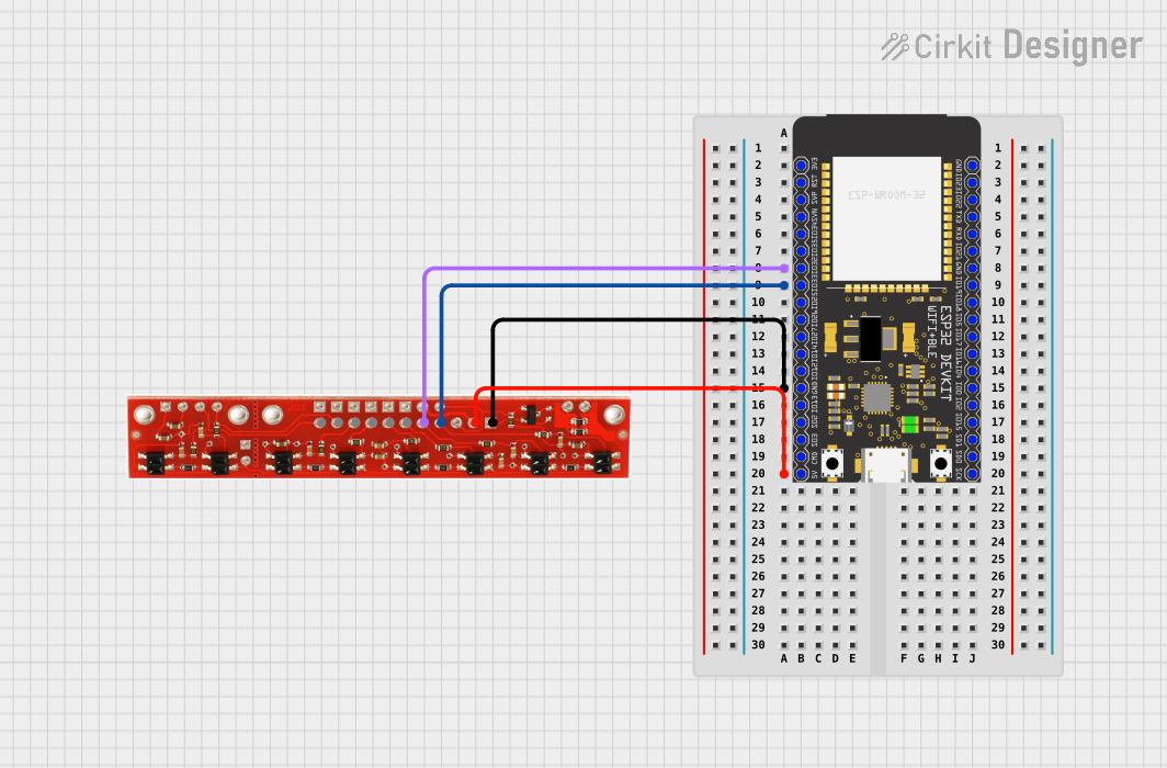
This circuit integrates an ESP32 Wroom microcontroller with a Line Sensor. The ESP32 Wroom is a powerful microcontroller with Wi-Fi and Bluetooth capabilities, which can be used for various IoT applications. The Line Sensor is typically used for detecting lines on the ground, often seen in robotics for path tracking. In this circuit, the ESP32 Wroom is configured to read signals from the Line Sensor to process line detection data.
Component List
ESP32 Wroom
- Description: A microcontroller with Wi-Fi and Bluetooth capabilities, suitable for a wide range of IoT applications.
- Pins:
- Power: 3V3, 5V, GND
- GPIO: 36, 39, 34, 35, 32, 33, 25, 26, 27, 14, 12, 13, 9, 10, 11, 23, 22, 1, 3, 21, 19, 18, 5, 17, 16, 4, 0, 2, 15, 8, 7, 6
Line Sensor
- Description: A sensor used to detect lines on the ground, commonly used in robotics.
- Pins:
- Signal: 8, 7, 6, 5, 4, 3, 2, 1
- Power: +5v, GND
Wiring Details
ESP32 Wroom
- GPIO32 connected to Line Sensor pin 2
- GPIO33 connected to Line Sensor pin 1
- GND connected to Line Sensor GND
- 5V connected to Line Sensor +5v
Line Sensor
- Pin 2 connected to ESP32 Wroom GPIO32
- Pin 1 connected to ESP32 Wroom GPIO33
- GND connected to ESP32 Wroom GND
- +5v connected to ESP32 Wroom 5V
Documented Code
No code has been provided for the microcontroller. The documentation of the code would typically include a description of the functionality, setup and loop functions for an Arduino-based microcontroller, or initialization and main loop for other microcontrollers, along with comments explaining the purpose of each section of the code. Since no code is available, this section cannot be completed.