
Arduino Nano-Based RGB LED Controller with Pushbutton Interface and Battery Power
View and Edit Project In Cirkit Designer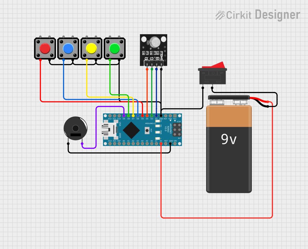
Circuit Documentation
Summary
This circuit consists of an Arduino Nano microcontroller, an RGB LED module, multiple pushbuttons, a piezo buzzer, a rocker switch, and a 9V battery. The circuit is designed to control the RGB LED and piezo buzzer based on the state of the pushbuttons and the rocker switch.
Component List
Arduino Nano
- Description: A small, complete, and breadboard-friendly board based on the ATmega328P.
- Pins: D1/TX, D0/RX, RESET, GND, D2, D3, D4, D5, D6, D7, D8, D9, D10, D11/MOSI, D12/MISO, VIN, 5V, A7, A6, A5, A4, A3, A2, A1, A0, AREF, 3V3, D13/SCK
RGB LED Module
- Description: A module containing an RGB LED that can emit different colors based on the input signals.
- Pins: +VCC Red, +VCC Green, +VCC Blue, GND
Pushbutton
- Description: A simple pushbutton switch.
- Pins: Pin 2, Pin 1, Pin 3, Pin 4
Piezo Buzzer
- Description: A small electronic device that produces a sound when a voltage is applied.
- Pins: pin 1, pin 2
Rocker Switch
- Description: A switch that can be toggled between two positions.
- Pins: 1, 2
9V Battery
- Description: A standard 9V battery used to power the circuit.
- Pins: -, +
Wiring Details
Arduino Nano
GND is connected to:
- GND of the RGB LED module
- Pin 3 of all pushbuttons
- pin 1 of the Piezo Buzzer
D2 is connected to +VCC Blue of the RGB LED module.
D3 is connected to +VCC Green of the RGB LED module.
D4 is connected to +VCC Red of the RGB LED module.
D5 is connected to Pin 2 of one pushbutton.
D6 is connected to Pin 2 of another pushbutton.
D7 is connected to Pin 2 of another pushbutton.
D8 is connected to Pin 2 of another pushbutton.
D9 is connected to pin 2 of the Piezo Buzzer.
5V is connected to + of the 9V Battery.
RGB LED Module
- GND is connected to GND of the Arduino Nano.
- +VCC Blue is connected to D2 of the Arduino Nano.
- +VCC Green is connected to D3 of the Arduino Nano.
- +VCC Red is connected to D4 of the Arduino Nano.
Pushbuttons
- Pin 3 of all pushbuttons is connected to GND of the Arduino Nano.
- Pin 2 of the first pushbutton is connected to D5 of the Arduino Nano.
- Pin 2 of the second pushbutton is connected to D6 of the Arduino Nano.
- Pin 2 of the third pushbutton is connected to D7 of the Arduino Nano.
- Pin 2 of the fourth pushbutton is connected to D8 of the Arduino Nano.
Piezo Buzzer
- pin 1 is connected to GND of the Arduino Nano.
- pin 2 is connected to D9 of the Arduino Nano.
Rocker Switch
- Pin 1 is connected to Pin 3 of all pushbuttons and GND of the RGB LED module.
- Pin 2 is connected to - of the 9V Battery.
9V Battery
- + is connected to 5V of the Arduino Nano.
- - is connected to Pin 2 of the Rocker Switch.
Documented Code
Arduino Nano Code (sketch.ino)
void setup() {
  // put your setup code here, to run once:

}

void loop() {
  // put your main code here, to run repeatedly:

}
Additional Documentation (documentation.txt)
This documentation provides a comprehensive overview of the circuit, including a summary, detailed component list, wiring details, and the code used in the microcontroller.