Cirkit Designer
Your all-in-one circuit design IDE
Home /
Project Documentation
Arduino UNO-Based Password-Protected Door Lock System with LCD Display and Keypad
Circuit Documentation
Summary
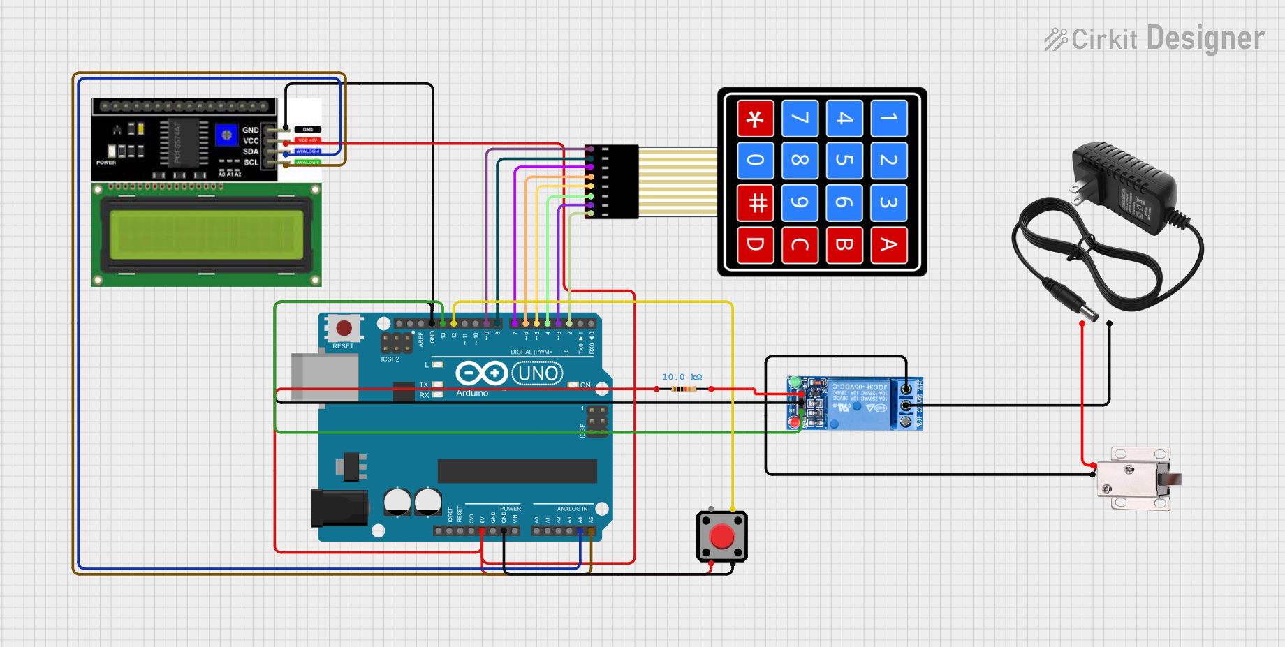
This circuit is designed to control a 12V solenoid lock using an Arduino UNO, a 4x4 membrane matrix keypad, an LCD I2C display, a 1-channel relay module, a red pushbutton, and a 12V power supply. The user can unlock the door by entering a correct password on the keypad or by pressing the exit button. The status and instructions are displayed on the LCD.
Component List
Arduino UNO
- Description: Microcontroller board based on the ATmega328P.
- Pins: UNUSED, IOREF, Reset, 3.3V, 5V, GND, Vin, A0, A1, A2, A3, A4, A5, SCL, SDA, AREF, D13, D12, D11, D10, D9, D8, D7, D6, D5, D4, D3, D2, D1, D0
LCD I2C Display
- Description: 16x2 character LCD display with I2C interface.
- Pins: GND, VCC, SDA, SCL
4X4 Membrane Matrix Keypad
- Description: Keypad with 4 rows and 4 columns.
- Pins: R1, R2, R3, R4, C1, C2, C3, C4
1 Channel Relay 5V
- Description: Relay module for switching high voltage devices.
- Pins: VCC, GND, IN, NC, COM, NO
12V Solenoid Lock
- Description: Electromechanical lock that operates on 12V.
- Pins: VCC, GND
Red Pushbutton
- Description: Pushbutton switch with 4 pins.
- Pins: Pin 2, Pin 1, Pin 3, Pin 4
12V Power Supply
- Description: Power supply providing 12V output.
- Pins: +, -
Resistor
- Description: 10k Ohm resistor.
- Pins: pin1, pin2
Wiring Details
Arduino UNO
- D9: Connected to R1 of the 4X4 Membrane Matrix Keypad
- D8: Connected to R2 of the 4X4 Membrane Matrix Keypad
- D7: Connected to R3 of the 4X4 Membrane Matrix Keypad
- D6: Connected to R4 of the 4X4 Membrane Matrix Keypad
- D5: Connected to C1 of the 4X4 Membrane Matrix Keypad
- D4: Connected to C2 of the 4X4 Membrane Matrix Keypad
- D3: Connected to C3 of the 4X4 Membrane Matrix Keypad
- D2: Connected to C4 of the 4X4 Membrane Matrix Keypad
- 5V: Connected to VCC of the LCD I2C Display and pin1 of the Resistor
- GND: Connected to GND of the LCD I2C Display, Pin 3 of the Red Pushbutton, and GND of the 1 Channel Relay 5V
- A4: Connected to SDA of the LCD I2C Display
- A5: Connected to SCL of the LCD I2C Display
- D13: Connected to IN of the 1 Channel Relay 5V
- D12: Connected to Pin 4 of the Red Pushbutton
LCD I2C Display
- GND: Connected to GND of the Arduino UNO
- VCC: Connected to 5V of the Arduino UNO and pin1 of the Resistor
- SDA: Connected to A4 of the Arduino UNO
- SCL: Connected to A5 of the Arduino UNO
4X4 Membrane Matrix Keypad
- R1: Connected to D9 of the Arduino UNO
- R2: Connected to D8 of the Arduino UNO
- R3: Connected to D7 of the Arduino UNO
- R4: Connected to D6 of the Arduino UNO
- C1: Connected to D5 of the Arduino UNO
- C2: Connected to D4 of the Arduino UNO
- C3: Connected to D3 of the Arduino UNO
- C4: Connected to D2 of the Arduino UNO
1 Channel Relay 5V
- VCC: Connected to pin2 of the Resistor
- GND: Connected to GND of the Arduino UNO
- IN: Connected to D13 of the Arduino UNO
- COM: Connected to - of the 12V Power Supply
- NO: Connected to GND of the 12V Solenoid Lock
12V Solenoid Lock
- VCC: Connected to + of the 12V Power Supply
- GND: Connected to NO of the 1 Channel Relay 5V
Red Pushbutton
- Pin 2: Connected to VCC of the LCD I2C Display and pin1 of the Resistor
- Pin 3: Connected to GND of the Arduino UNO
- Pin 4: Connected to D12 of the Arduino UNO
12V Power Supply
- +: Connected to VCC of the 12V Solenoid Lock
- -: Connected to COM of the 1 Channel Relay 5V
Resistor
- pin1: Connected to VCC of the LCD I2C Display and 5V of the Arduino UNO
- pin2: Connected to VCC of the 1 Channel Relay 5V
Documented Code
#include <Wire.h>
#include <LiquidCrystal_I2C.h>
#include <Keypad.h>

// Define the pins
const int relayPin = 13;       // Pin connected to the relay module
const int exitButtonPin = 12;  // Pin connected to the exit button

// LCD setup: I2C address, columns, rows
LiquidCrystal_I2C lcd(0x27, 16, 2); // 0x27 is the typical I2C address, 16 columns, 2 rows

// Keypad setup
const byte ROWS = 4; // Four rows
const byte COLS = 4; // Four columns
char keys[ROWS][COLS] = {
  {'1', '2', '3', 'A'},
  {'4', '5', '6', 'B'},
  {'7', '8', '9', 'C'},
  {'*', '0', '#', 'D'}
};
byte rowPins[ROWS] = {9, 8, 7, 6};    // Connect to the row pinouts of the keypad
byte colPins[COLS] = {5, 4, 3, 2};    // Connect to the column pinouts of the keypad

// Initialize the Keypad
Keypad keypad = Keypad(makeKeymap(keys), rowPins, colPins, ROWS, COLS);

// Password setup
String password = "1234"; // Correct password
String input = "";        // Variable to store user input

// Exit button debounce variables
bool exitButtonState = LOW;          // Current state of the exit button
bool lastExitButtonState = LOW;      // Previous state of the exit button
unsigned long exitButtonLastTime = 0; // Last time the button was toggled
const unsigned long debounceDelay = 50; // Debounce time in milliseconds

void setup() {
  // Initialize the relay and exit button pins
  pinMode(relayPin, OUTPUT);
  pinMode(exitButtonPin, INPUT_PULLUP); // Configure the exit button with an internal pull-up resistor
  digitalWrite(relayPin, LOW);          // Ensure relay is OFF initially

  // Initialize the LCD
  lcd.begin(16, 2);       // 16 columns, 2 rows
  lcd.backlight();        // Turn on the backlight
  lcd.print("Enter Password:"); // Display initial message

  // Begin Serial Monitor (optional for debugging)
  Serial.begin(9600);
}

void loop() {
  handleExitButton(); // Check and handle the exit button

  // Check keypad input
  char key = keypad.getKey(); // Get keypress
  if (key) {
    if (key == '*') { // Clear input if '*' is pressed
      input = ""; // Clear input
      lcd.clear();
      lcd.print("Input Cleared!");
      delay(1000);
      lcd.clear();