
Raspberry Pi Zero W-Based Handheld Gaming Console with LCD Display
View and Edit Project In Cirkit Designer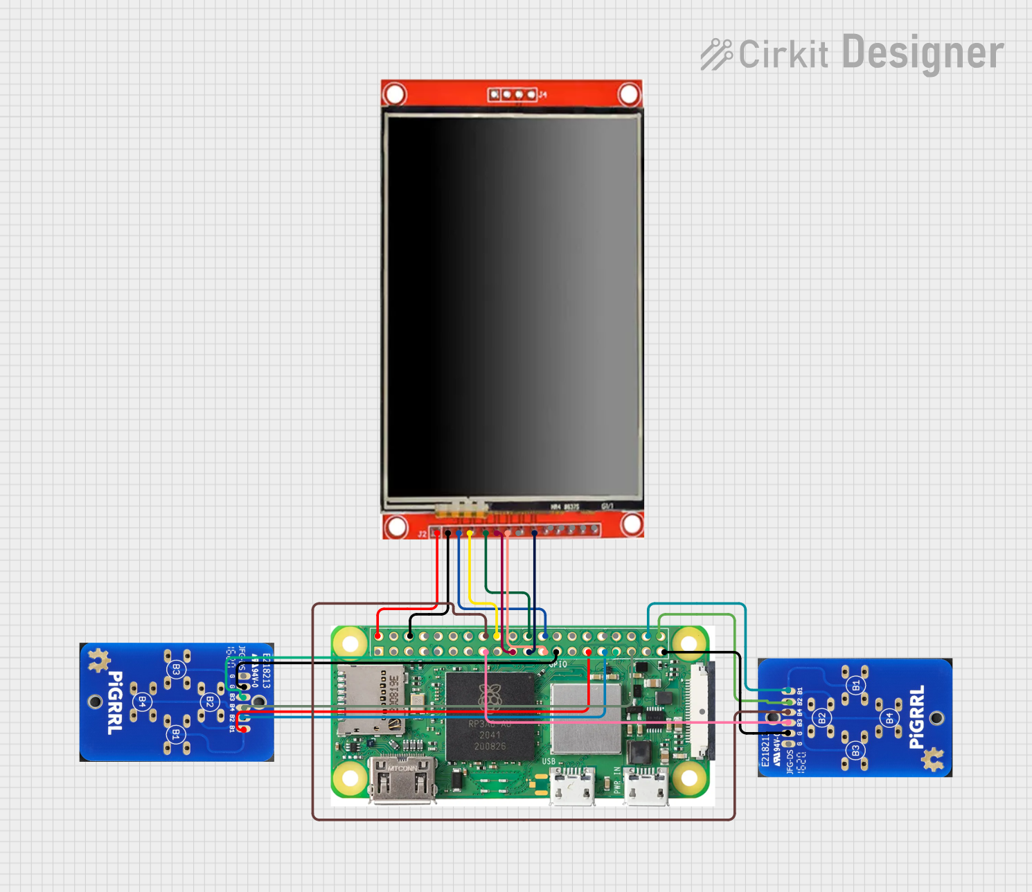
Circuit Documentation
Summary
This circuit integrates a Raspberry Pi Zero W with an LCD TFT screen (ILI9488 HD) and two instances of a PiGrrl Zero Custom Gamepad PCB. The Raspberry Pi Zero W serves as the central processing unit, managing the display output to the LCD screen and receiving input from the gamepad PCBs. The LCD screen is used for visual output, while the gamepad PCBs are used as input devices with multiple buttons.
Component List
Raspberry Pi Zero W
- Description: A low-cost, compact version of the Raspberry Pi with wireless LAN and Bluetooth connectivity.
- Pins: 5V, 3V3, multiple GPIOs, GND, CSI (Camera)
LCD TFT Screen ILI9488 HD
- Description: A color TFT LCD screen with an ILI9488 HD driver, suitable for displaying high-definition graphics.
- Pins: PEN, TDO, TDI, VCC (3.3~5V), GND, CS, RST, D/C, SDI(MOSI), SCK, BL, SDO(MISO), TCS, TCK
PiGrrl Zero Custom Gamepad PCB (Two Instances)
- Description: A custom gamepad PCB designed for use with the PiGrrl Zero project, featuring multiple buttons for user input.
- Pins: G, B1, B2, B3, B4
Wiring Details
Raspberry Pi Zero W
- 5V connected to LCD TFT screen ILI9488 HD VCC (3.3~5V)
- GROUND connected to LCD TFT screen ILI9488 HD GND
- GPIO 23 connected to PiGrrl Zero Custom Gamepad PCB B4
- GPIO 24 connected to LCD TFT screen ILI9488 HD RST
- GPIO 25 connected to LCD TFT screen ILI9488 HD D/C
- GPIO 8 connected to LCD TFT screen ILI9488 HD CS
- GPIO 20 connected to PiGrrl Zero Custom Gamepad PCB B1
- GPIO 21 connected to PiGrrl Zero Custom Gamepad PCB B2
- GPIO 22 connected to PiGrrl Zero Custom Gamepad PCB B3
- GPIO 10 connected to LCD TFT screen ILI9488 HD SDI(MOSI)
- GPIO 9 connected to LCD TFT screen ILI9488 HD SDO(MISO)
- GPIO 11 connected to LCD TFT screen ILI9488 HD SCK
- GND connected to PiGrrl Zero Custom Gamepad PCB G (for both instances)
- GPIO 5 connected to PiGrrl Zero Custom Gamepad PCB B1
- GPIO 6 connected to PiGrrl Zero Custom Gamepad PCB B2
- GPIO 13 connected to PiGrrl Zero Custom Gamepad PCB B3
- GPIO 19 connected to PiGrrl Zero Custom Gamepad PCB B4
LCD TFT Screen ILI9488 HD
- VCC (3.3~5V) connected to Raspberry Pi Zero W 5V
- GND connected to Raspberry Pi Zero W GROUND
- CS connected to Raspberry Pi Zero W GPIO 8
- RST connected to Raspberry Pi Zero W GPIO 24
- D/C connected to Raspberry Pi Zero W GPIO 25
- SDI(MOSI) connected to Raspberry Pi Zero W GPIO 10
- SCK connected to Raspberry Pi Zero W GPIO 11
- SDO(MISO) connected to Raspberry Pi Zero W GPIO 9
PiGrrl Zero Custom Gamepad PCB (Instance 1)
- G connected to Raspberry Pi Zero W GND
- B1 connected to Raspberry Pi Zero W GPIO 5
- B2 connected to Raspberry Pi Zero W GPIO 6
- B3 connected to Raspberry Pi Zero W GPIO 13
- B4 connected to Raspberry Pi Zero W GPIO 19
PiGrrl Zero Custom Gamepad PCB (Instance 2)
- G connected to Raspberry Pi Zero W GND
- B1 connected to Raspberry Pi Zero W GPIO 20
- B2 connected to Raspberry Pi Zero W GPIO 21
- B3 connected to Raspberry Pi Zero W GPIO 22
- B4 connected to Raspberry Pi Zero W GPIO 23
Code Documentation
No code has been provided for the microcontrollers in the circuit. If code is later provided, it should be documented here with details on how it interfaces with the hardware components, including setup, main loop, and any interrupt service routines or peripheral configurations.