Cirkit Designer
Your all-in-one circuit design IDE
Home /
Project Documentation
Arduino UNO Controlled RGB LED and DHT11 Temperature Sensor Circuit
Circuit Documentation
Summary
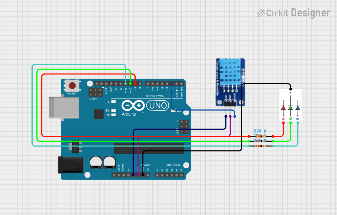
This circuit is designed to interface an RGB LED and a DHT11 temperature and humidity sensor with an Arduino UNO microcontroller. The Arduino UNO controls the RGB LED color based on the temperature readings from the DHT11 sensor. The circuit uses resistors to limit the current to the RGB LED. The DHT11 sensor provides the ambient temperature and humidity data to the Arduino, which then adjusts the color of the RGB LED accordingly.
Component List
Resistor
- Description: A resistor is a passive two-terminal electrical component that implements electrical resistance as a circuit element.
- Purpose: In this circuit, resistors are used to limit the current flowing through the RGB LED to prevent damage.
- Properties: 220 Ohms
RGB LED
- Description: An RGB LED is a light-emitting diode that can emit red, green, and blue light, and by mixing these colors, it can produce a wide spectrum of colors.
- Purpose: The RGB LED displays different colors based on the temperature readings from the DHT11 sensor.
- Pins: B (Blue), G (Green), R (Red), GND (Ground)
Arduino UNO
- Description: The Arduino UNO is a microcontroller board based on the ATmega328P. It has digital input/output pins, analog inputs, a USB connection for programming, and power.
- Purpose: It serves as the central controller for the circuit, reading sensor data and controlling the RGB LED.
- Pins: Various digital and analog pins, power, and ground.
DHT11
- Description: The DHT11 is a basic, ultra-low-cost digital temperature and humidity sensor.
- Purpose: It measures the surrounding air temperature and humidity, providing data to the Arduino UNO.
- Pins: DATA, GND (Ground), VCC (Power)
Wiring Details
Resistor (220 Ohms)
- Connected between the Arduino UNO digital pins (D10, D11, D9) and the RGB LED pins (G, B, R).
RGB LED
- Blue Pin (B): Connected to a 220 Ohm resistor, then to Arduino UNO pin D11.
- Green Pin (G): Connected to a 220 Ohm resistor, then to Arduino UNO pin D10.
- Red Pin (R): Connected to a 220 Ohm resistor, then to Arduino UNO pin D9.
- Ground (GND): Connected to the Arduino UNO GND pin.
Arduino UNO
- Digital Pin D10: Connected to a resistor, then to the green pin of the RGB LED.
- Digital Pin D11: Connected to a resistor, then to the blue pin of the RGB LED.
- Digital Pin D9: Connected to a resistor, then to the red pin of the RGB LED.
- Digital Pin D2: Connected to the DATA pin of the DHT11 sensor.
- 5V Pin: Provides power to the DHT11 sensor.
- GND Pin: Connected to the ground pins of both the RGB LED and the DHT11 sensor.
DHT11
- DATA Pin: Connected to Arduino UNO digital pin D2.
- Ground (GND) Pin: Connected to the Arduino UNO GND pin.
- Power (VCC) Pin: Connected to the Arduino UNO 5V pin.
Documented Code
#include <DHT.h>

#define DHTPIN 2     // Digital pin connected to the DHT sensor
#define DHTTYPE DHT11   // DHT 11

DHT dht(DHTPIN, DHTTYPE);

#define RED_PIN 9
#define GREEN_PIN 10
#define BLUE_PIN 11

void setup() {
  Serial.begin(9600);
  dht.begin();
  pinMode(RED_PIN, OUTPUT);
  pinMode(GREEN_PIN, OUTPUT);
  pinMode(BLUE_PIN, OUTPUT);
}

void loop() {
  float h = dht.readHumidity();
  float t = dht.readTemperature();

  if (isnan(h) || isnan(t)) {
    Serial.println("Failed to read from DHT sensor!");
    return;
  }

  Serial.print("Temperature: ");
  Serial.print(t);
  Serial.println(" *C");

  // Change LED color based on the temperature
  if (t > 30) { // High temperature
    setColor(255, 0, 0); // Red
  } else if (t >= 20 && t <= 30) { // Moderate temperature
    setColor(0, 255, 0); // Green
  } else { // Low temperature
    setColor(255, 255, 0); // Yellow
  }

  delay(2000); // Wait for two seconds before the next reading
}

void setColor(int red, int green, int blue) {
  analogWrite(RED_PIN, red);
  analogWrite(GREEN_PIN, green);
  analogWrite(BLUE_PIN, blue);
}
The code initializes the DHT11 sensor and configures the RGB LED pins as outputs. In the main loop, it reads the temperature and humidity from the DHT11 sensor. Depending on the temperature value, it sets the RGB LED to red, green, or yellow. The setColor function uses PWM to set the color of the RGB LED.