
Circuit Documentation
Summary
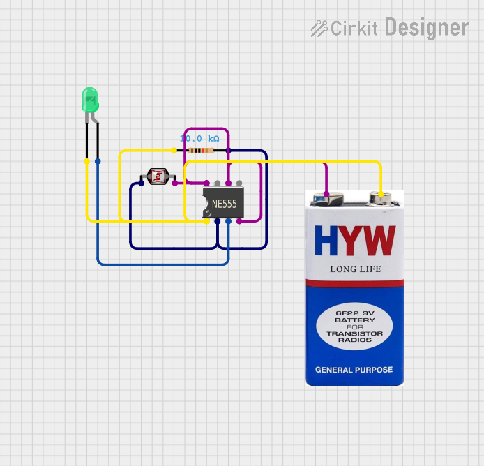
This circuit appears to be a light-sensitive timer circuit that uses a 555 Timer IC in conjunction with a photocell (LDR) to control the illumination of an LED based on ambient light levels. The 555 Timer IC is configured in a way that it likely provides a constant output while the photocell detects a certain light threshold. The LED is used as an output indicator, and a resistor is included to set the sensitivity of the photocell or to limit the current through the LED. The circuit is powered by a 9V battery.
Component List
555 Timer IC
- Description: A highly stable device for generating accurate time delays or oscillation.
- Pins: VCC+, Dis, Th, CV, Rst, Out, Trig, GND
Photocell (LDR)
- Description: A light-dependent resistor whose resistance changes based on the ambient light level.
- Pins: pin 0, pin 1
LED: Two Pin (green)
- Description: A green light-emitting diode used as an indicator or for lighting purposes.
- Pins: cathode, anode
Resistor
- Description: A passive two-terminal electrical component that implements electrical resistance as a circuit element.
- Resistance: 10000 Ohms
9V Battery
- Description: A standard 9V battery used as the power source for the circuit.
- Pins: +, -
Wiring Details
555 Timer IC
- VCC+: Connected to the positive terminal of the 9V battery, pin 1 of the Photocell (LDR), and the Th and Rst pins of the 555 Timer IC itself.
- Dis: Not connected in the provided net list.
- Th: Connected to VCC+.
- CV: Not connected in the provided net list.
- Rst: Connected to VCC+.
- Out: Connected to the anode of the LED.
- Trig: Connected to pin 0 of the Photocell (LDR) and pin 2 of the Resistor.
- GND: Connected to the negative terminal of the 9V battery, cathode of the LED, and pin 1 of the Resistor.
Photocell (LDR)
- pin 0: Connected to the Trig pin of the 555 Timer IC and pin 2 of the Resistor.
- pin 1: Connected to the positive terminal of the 9V battery and the VCC+ of the 555 Timer IC.
LED: Two Pin (green)
- cathode: Connected to the GND pin of the 555 Timer IC and pin 1 of the Resistor.
- anode: Connected to the Out pin of the 555 Timer IC.
Resistor
- pin1: Connected to the cathode of the LED and the GND pin of the 555 Timer IC.
- pin2: Connected to pin 0 of the Photocell (LDR) and the Trig pin of the 555 Timer IC.
9V Battery
- +: Connected to the VCC+ of the 555 Timer IC and pin 1 of the Photocell (LDR).
- -: Connected to the GND pin of the 555 Timer IC.
Documented Code
There is no embedded code provided for any microcontrollers in this circuit. The 555 Timer IC operates based on its pin configurations and does not require programming. If in the future, a microcontroller is added to the circuit, the code section will be updated accordingly.