Arduino UNO Controlled Motorized Drawer with Clap Activation and LED Indicator
Circuit Documentation
Summary
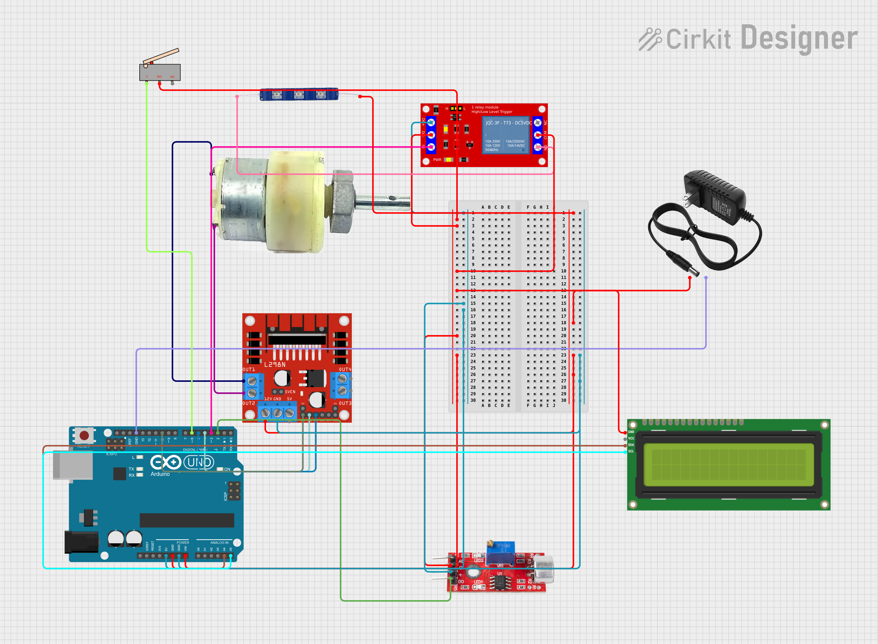
This circuit is designed to control a 12V geared motor and a blue LED using an Arduino UNO microcontroller based on input from a sound sensor and a limit switch. The motor's direction is controlled by an L298N DC motor driver, and the LED is switched on and off using a 1-channel 5V relay module. The system also includes a 12V power supply to power the motor and the LED. An I2C LCD screen is used to display the system status.
Component List
Arduino UNO
- Microcontroller board based on the ATmega328P
- Provides I/O pins and power to various components in the circuit
12V Geared Motor
- A motor that converts electrical energy into mechanical energy
- Operated by the L298N motor driver
12V Power Supply
- Provides the necessary power to the motor and the LED
12V Blue LED
- An indicator light that illuminates when the relay is activated
L298N DC Motor Driver
- An H-bridge motor driver that allows for the control of the motor's direction
Sound Sensor
- Detects sound and sends a digital signal to the Arduino
1 Channel 5V Relay Module
- Controls high power devices, such as the LED, using a low power signal from the Arduino
Limit Switch
- A switch that will be activated when a moving part reaches a certain point
I2C LCD 16x2 Screen
- Displays text information regarding the system status
Wiring Details
Arduino UNO
5Vto Relay ModuleVCC+, Sound SensorVCCGNDto Limit SwitchNO, Relay ModuleVCC- (GND),COM, I2C LCD ScreenGND, Sound SensorGND, L298N Motor DriverGNDVinto 12V Power Supply+, 12V Blue LEDVCC, L298N Motor Driver12VA4to I2C LCD ScreenSDAA5to I2C LCD ScreenSCLD10to L298N Motor DriverENAD6to Limit SwitchCD5to L298N Motor DriverIN2D4to L298N Motor DriverIN1D3to Relay ModuleIND2to Sound SensorDigital
12V Geared Motor
Terminal 1to L298N Motor DriverOUT1Terminal 2to L298N Motor DriverOUT2
12V Power Supply
-to Arduino UNOGND
12V Blue LED
GNDto Relay ModuleN.O.
L298N DC Motor Driver
GNDto Arduino UNOGND12Vto Arduino UNOVinENAto Arduino UNOD10IN1to Arduino UNOD4IN2to Arduino UNOD5OUT1to 12V Geared MotorTerminal 1OUT2to 12V Geared MotorTerminal 2
Sound Sensor
VCCto Arduino UNO5VGNDto Arduino UNOGNDDigitalto Arduino UNOD2
1 Channel 5V Relay Module
VCC+to Arduino UNO5VVCC- (GND)to Arduino UNOGNDINto Arduino UNOD3COMto Arduino UNOGNDN.O.to 12V Blue LEDGND
Limit Switch
Cto Arduino UNOD6NOto Arduino UNOGND
I2C LCD 16x2 Screen
SDAto Arduino UNOA4SCLto Arduino UNOA5GNDto Arduino UNOGND
Documented Code
#include <Wire.h>
#include <LiquidCrystal_I2C.h>

// Pin Definitions
const int soundSensorPin = 2;       // Digital pin for sound sensor
const int relayPin = 3;             // Digital pin for relay (LED)
const int motorForwardPin = 4;      // Motor driver forward control pin
const int motorBackwardPin = 5;     // Motor driver backward control pin
const int limitSwitchPin = 6;       // Limit switch pin

// LCD Setup
LiquidCrystal_I2C lcd(0x27, 16, 2); // Adjust address as necessary

// State Variables
bool drawerOpen = false;

void setup() {
    // Initialize pins
    pinMode(soundSensorPin, INPUT);
    pinMode(relayPin, OUTPUT);
    pinMode(motorForwardPin, OUTPUT);
    pinMode(motorBackwardPin, OUTPUT);
    pinMode(limitSwitchPin, INPUT_PULLUP); // Use internal pull-up resistor

    // Initialize LCD
    lcd.begin();
    lcd.backlight();
    lcd.print("Ready to Clap");
}

void loop() {
    // Check for clap
    if (digitalRead(soundSensorPin) == HIGH) {
        delay(200); // Debounce delay for sound sensor

        if (!drawerOpen) {
            openDrawer();
        } else {
            closeDrawer();
        }

        // Wait until clap is no longer detected
        while (digitalRead(soundSensorPin) == HIGH) {
            delay(50);
        }
    }
}

void openDrawer() {
    digitalWrite(relayPin, HIGH); // Turn on LED
    lcd.clear();
    lcd.print("Opening Drawer");
    digitalWrite(motorForwardPin, HIGH); // Move motor forward

    // Run motor until limit switch is pressed
    while (digitalRead(limitSwitchPin) == HIGH) {
        delay(50); // Debounce limit switch
    }

    digitalWrite(motorForwardPin, LOW); // Stop motor
    drawerOpen = true;
    lcd.clear();
    lcd.print("Drawer Open");
    delay(1000); // Pause to display message
    lcd.clear();
    lcd.print("Ready to Clap");
}

void closeDrawer() {
    digitalWrite(relayPin, LOW); // Turn off LED
    lcd.clear();
    lcd.print("Closing Drawer");
    digitalWrite(motorBackwardPin, HIGH); // Move motor backward

    // Run motor until limit switch is released
    while (digitalRead(limitSwitchPin) == LOW) {
        delay(50); // Debounce limit switch
    }

    digitalWrite(motorBackwardPin, LOW); // Stop motor
    drawerOpen = false;
    lcd.clear();
    lcd.print("Drawer Closed");
    delay(1000); // Pause to display message
    lcd.clear();
    lcd.print("Ready to Clap");
}
This code is designed to run on the Arduino UNO and controls the motor, LED, and LCD based on input from the sound sensor and limit switch. When a clap is detected by the sound sensor, the system will either open or close a drawer, indicated by the motor's movement and the LED's state. The LCD provides feedback on the system's status.