
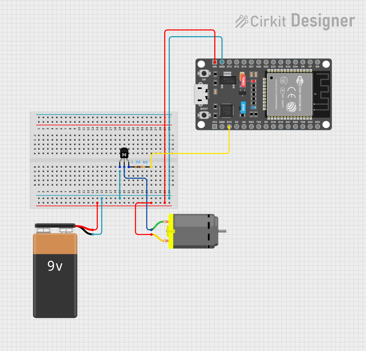
Circuit Documentation
Summary
This circuit is designed to control a DC motor using an ESP32 microcontroller and an NPN transistor. The motor can be turned on and off via Bluetooth commands sent to the ESP32. The circuit includes a 9V battery to power the motor, a resistor to limit the current to the transistor's base, and the ESP32 to handle Bluetooth communication and control signals.
Component List
DC Motor
- Description: A motor that converts electrical energy into mechanical motion.
- Pins: pin 1, pin 2
NPN Transistor (ECB)
- Description: A transistor used to switch the motor on and off.
- Pins: emitter, collector, base
Resistor
- Description: A resistor used to limit the current to the transistor's base.
- Pins: pin1, pin2
- Properties:
- Resistance: 1000 Ohms
ESP32 DEVKIT V1 (30 pins)
- Description: A microcontroller used to control the motor via Bluetooth.
- Pins: EN, VP, VN, D34, D35, D32, D33, D25, D26, D27, D14, D12, D13, GND, VIN, 3V3, D15, D2, D4, RX2, TX2, D5, D18, D19, D21, RX0, TX0, D22, D23
9V Battery
- Description: A battery used to power the motor.
- Pins: -, +
Wiring Details
DC Motor
- pin 1: Connected to the collector of the NPN Transistor.
- pin 2: Connected to the positive terminal of the 9V Battery and VIN pin of the ESP32.
NPN Transistor (ECB)
- emitter: Connected to the negative terminal of the 9V Battery and GND pin of the ESP32.
- collector: Connected to pin 1 of the DC Motor.
- base: Connected to pin1 of the Resistor.
Resistor
- pin1: Connected to the base of the NPN Transistor.
- pin2: Connected to D15 pin of the ESP32.
ESP32 DEVKIT V1 (30 pins)
- GND: Connected to the emitter of the NPN Transistor and the negative terminal of the 9V Battery.
- VIN: Connected to the positive terminal of the 9V Battery and pin 2 of the DC Motor.
- D15: Connected to pin2 of the Resistor.
9V Battery
- -: Connected to the emitter of the NPN Transistor and GND pin of the ESP32.
- +: Connected to pin 2 of the DC Motor and VIN pin of the ESP32.
Code Documentation
Bluetooth Motor Control Code
#include "BluetoothSerial.h" // Include BluetoothSerial library

// Define motor control pin
#define MOTOR_PIN 15

// Create a BluetoothSerial object
BluetoothSerial ESP_BT;

// Variable to track motor state
bool motorState = false;

void setup() {
  // Initialize Serial Monitor
  Serial.begin(115200);
  Serial.println("Starting ESP32 Bluetooth Motor Control...");

  // Initialize Bluetooth
  if (!ESP_BT.begin("ESP32_Motor_Control")) {
    Serial.println("Bluetooth initialization failed!");
    while (1);
  }
  Serial.println("Bluetooth initialized. Waiting for connection...");

  // Set up motor pin as output
  pinMode(MOTOR_PIN, OUTPUT);
  digitalWrite(MOTOR_PIN, LOW); // Motor off by default
}

void loop() {
  // Check if data is available via Bluetooth
  if (ESP_BT.available()) {
    String command = ESP_BT.readString(); // Read the incoming command
    command.trim(); // Remove any extra whitespace
    Serial.print("Received command: ");
    Serial.println(command);

    // Turn motor ON
    if (command == "ON") {
      motorState = true;
      digitalWrite(MOTOR_PIN, HIGH); // Turn motor on
      ESP_BT.println("Motor is ON");
    }
    // Turn motor OFF
    else if (command == "OFF") {
      motorState = false;
      digitalWrite(MOTOR_PIN, LOW); // Turn motor off
      ESP_BT.println("Motor is OFF");
    }
    // Invalid command
    else {
      ESP_BT.println("Invalid command. Use 'ON' or 'OFF'.");
    }
  }
}
This code initializes the ESP32 for Bluetooth communication and sets up a motor control pin. It listens for Bluetooth commands to turn the motor on or off and responds accordingly.