
Arduino-Based Real-Time Clock Display with Adafruit LED Backpack
View and Edit Project In Cirkit Designer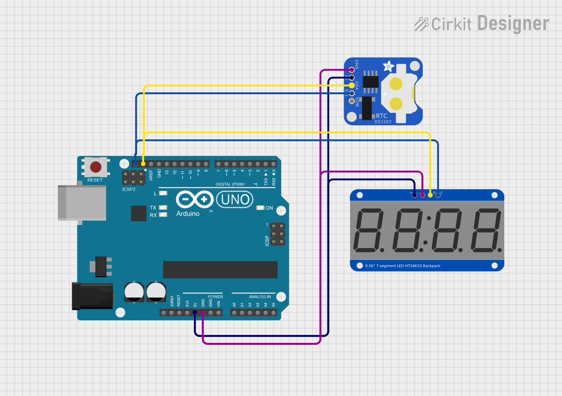
Circuit Documentation
Summary
This circuit is designed to read the current time from a DS1307 Real-Time Clock (RTC) and display it on an Adafruit 0.56 inch 7-segment LED Backpack. The Arduino UNO microcontroller is used to manage the I2C communication between the RTC and the LED display. The time is updated on the LED display every second, providing a real-time clock functionality.
Component List
Arduino UNO
- Description: A microcontroller board based on the ATmega328P. It is used to control the circuit and manage communication between components.
- Purpose: Acts as the main controller for reading time from the RTC and displaying it on the LED display.
DS1307 RTC
- Description: A Real-Time Clock (RTC) module that keeps track of the current time and date.
- Purpose: Provides accurate timekeeping to the Arduino, which is then displayed on the LED.
Adafruit 0.56 inch 7-segment LED Backpack
- Description: A compact LED display module that can show numbers and characters.
- Purpose: Displays the current time received from the DS1307 RTC.
Wiring Details
Arduino UNO
5V: Connected to the 5V pin of the DS1307 RTC and the VDD pin of the Adafruit LED Backpack.
GND: Connected to the GND pin of the DS1307 RTC and the GND pin of the Adafruit LED Backpack.
SCL: Connected to the SCL pin of the DS1307 RTC and the SCL pin of the Adafruit LED Backpack.
SDA: Connected to the SDA pin of the DS1307 RTC and the SDA pin of the Adafruit LED Backpack.
DS1307 RTC
5V: Connected to the 5V pin of the Arduino UNO and the VDD pin of the Adafruit LED Backpack.
GND: Connected to the GND pin of the Arduino UNO and the GND pin of the Adafruit LED Backpack.
SCL: Connected to the SCL pin of the Arduino UNO and the SCL pin of the Adafruit LED Backpack.
SDA: Connected to the SDA pin of the Arduino UNO and the SDA pin of the Adafruit LED Backpack.
Adafruit 0.56 inch 7-segment LED Backpack
VDD: Connected to the 5V pin of the Arduino UNO and the 5V pin of the DS1307 RTC.
GND: Connected to the GND pin of the Arduino UNO and the GND pin of the DS1307 RTC.
SCL: Connected to the SCL pin of the Arduino UNO and the SCL pin of the DS1307 RTC.
SDA: Connected to the SDA pin of the Arduino UNO and the SDA pin of the DS1307 RTC.
Documented Code
/*
 * Arduino Sketch for reading time from a DS1307 RTC and displaying it on an
 * Adafruit LED Backpack. The circuit uses I2C communication to interface with
 * both the RTC and the LED display. The time is read from the RTC and updated
 * on the LED display every second.
 */

#include <Wire.h>
#include <RTClib.h>
#include <Adafruit_GFX.h>
#include <Adafruit_LEDBackpack.h>

// Create RTC and LED display objects
RTC_DS1307 rtc;
Adafruit_7segment display = Adafruit_7segment();

void setup() {
  // Initialize I2C communication
  Wire.begin();

  // Initialize RTC
  if (!rtc.begin()) {
    // If RTC is not found, halt the program
    while (1);
  }

  // Check if the RTC is running
  if (!rtc.isrunning()) {
    // Set the RTC to the date & time this sketch was compiled
    rtc.adjust(DateTime(F(__DATE__), F(__TIME__)));
  }

  // Initialize the LED display
  display.begin(0x70); // Default I2C address for the backpack
}

void loop() {
  DateTime now = rtc.now();

  int h = now.hour();
  int m = now.minute();

  // Convert to 12-hour format
  int h12 = h % 12;
  if (h12 == 0) h12 = 12;

  display.clear();

  // Hours
  if (h12 >= 10) {
    display.writeDigitNum(0, h12 / 10);  // tens of hour
  }
  display.writeDigitNum(1, h12 % 10);     // ones of hour

  // Colon on
  display.drawColon(true);

  // Minutes
  display.writeDigitNum(3, m / 10);       // tens of minute
  display.writeDigitNum(4, m % 10);       // ones of minute

  display.writeDisplay();
  delay(1000);
}
This documentation provides a comprehensive overview of the circuit, detailing the components used, their connections, and the code that drives the functionality of the system.