Arduino-Controlled Quadcopter with Wireless Communication

Circuit Documentation
Summary
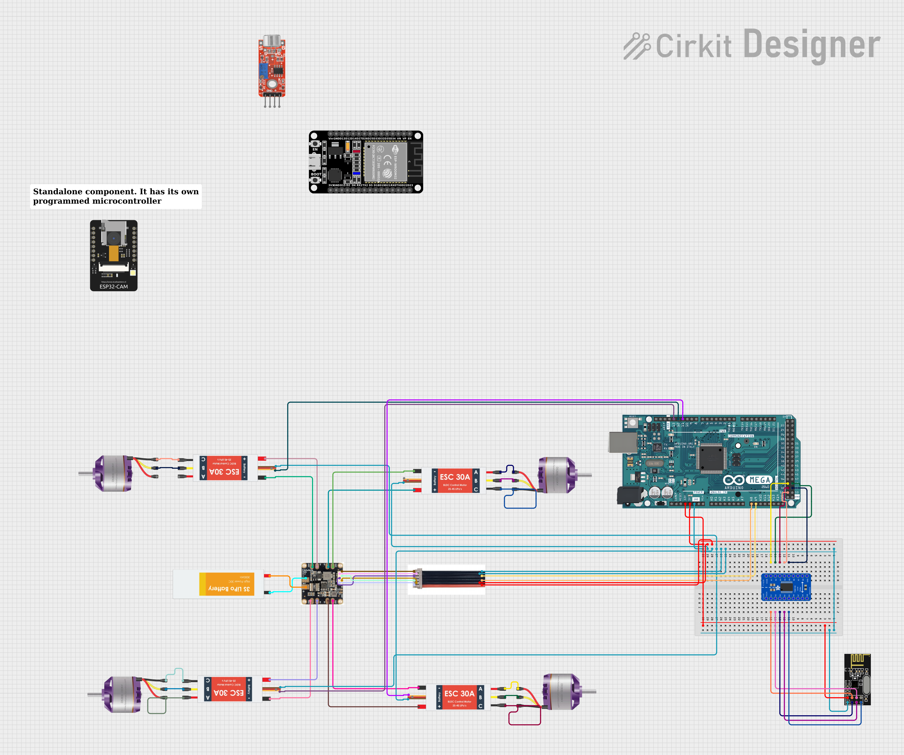
This circuit is designed to control four brushless motors using corresponding electronic speed controllers (ESCs). It includes a power management module (Pm06 v2-14s) to distribute power from a Lipo battery to the ESCs and other components. The Arduino Mega 2560 serves as the main microcontroller, interfacing with an NRF24L01 wireless module for remote communication. A logic level converter is used to safely interface the 3.3V logic of the NRF24L01 with the 5V logic of the Arduino Mega. Additionally, a 6pin JST-GH Cable is used for voltage and current sensing from the power management module to the Arduino. The circuit is designed for applications such as drones or other remote-controlled vehicles where precise motor control is required.
Component List
- Brushless Motors: Four motors that convert electrical energy into mechanical energy.
- Electronic Speed Controllers (ESC): Four controllers that regulate the speed and direction of the brushless motors.
- Pm06 v2-14s: A power management module that distributes power from the battery to the ESCs and other components.
- Lipo Battery: A rechargeable battery that provides power to the circuit.
- 6pin JST-GH Cable: A cable used for voltage and current sensing from the power management module to the Arduino.
- Arduino Mega 2560: The main microcontroller that controls the ESCs and interfaces with the NRF24L01 module.
- NRF24L01: A wireless communication module that allows remote control of the circuit.
- Adafruit TXB0108 8-channel Bi-directional Logic Level Converter: A device that safely steps down the 5V signals from the Arduino to 3.3V for the NRF24L01 and vice versa.
Wiring Details
Brushless Motors
- Motor 1: Connected to ESC 1 (M1, M2, M3 to L1, L2, L3)
- Motor 2: Connected to ESC 2 (M1, M2, M3 to L1, L2, L3)
- Motor 3: Connected to ESC 3 (M1, M2, M3 to L1, L2, L3)
- Motor 4: Connected to ESC 4 (M1, M2, M3 to L1, L2, L3)
Electronic Speed Controllers (ESC)
- ESC 1: Battery VCC and GND connected to Pm06 v2-14s (B+, GND), Signal connected to Arduino Mega (D12 PWM)
- ESC 2: Battery VCC and GND connected to Pm06 v2-14s (B+, GND), Signal connected to Arduino Mega (D13 PWM)
- ESC 3: Battery VCC and GND connected to Pm06 v2-14s (B+, GND), Signal connected to Arduino Mega (D11 PWM)
- ESC 4: Battery VCC and GND connected to Pm06 v2-14s (B+, GND), Signal connected to Arduino Mega (D10 PWM)
Pm06 v2-14s
- Power Input: Connected to Lipo Battery (BAT +, BAT -)
- Power Output: Connected to each ESC (B+, GND)
- Sensing: Connected to 6pin JST-GH Cable (V, I, 5v, GND)
Lipo Battery
- Power: Provides power to Pm06 v2-14s (VCC, GND)
6pin JST-GH Cable
- Sensing: Connected to Pm06 v2-14s (V, I, 5v, GND) and Arduino Mega (A8, A9, 5V, GND)
Arduino Mega 2560
- Control: Sends PWM signals to ESCs for motor control
- Sensing: Receives voltage and current data from Pm06 v2-14s via 6pin JST-GH Cable
- Communication: Interfaces with NRF24L01 through logic level converter
NRF24L01
- Communication: Wireless communication module connected to Arduino Mega via logic level converter
Adafruit TXB0108 8-channel Bi-directional Logic Level Converter
- Level Shifting: Steps down 5V signals from Arduino Mega to 3.3V for NRF24L01 and vice versa
Documented Code
Arduino Mega 2560 Code (sketch.ino)
void setup() {
  // put your setup code here, to run once:

}

void loop() {
  // put your main code here, to run repeatedly:

}
This code is a template for the Arduino Mega 2560. The setup() function runs once when the microcontroller is powered on or reset. The loop() function runs continuously after setup() has completed. The user will need to add the specific code for initializing the ESCs, reading sensor data, and handling wireless communication with the NRF24L01 module.