Arduino UNO Controlled Dual Servo Joystick Interface
Circuit Documentation
Summary
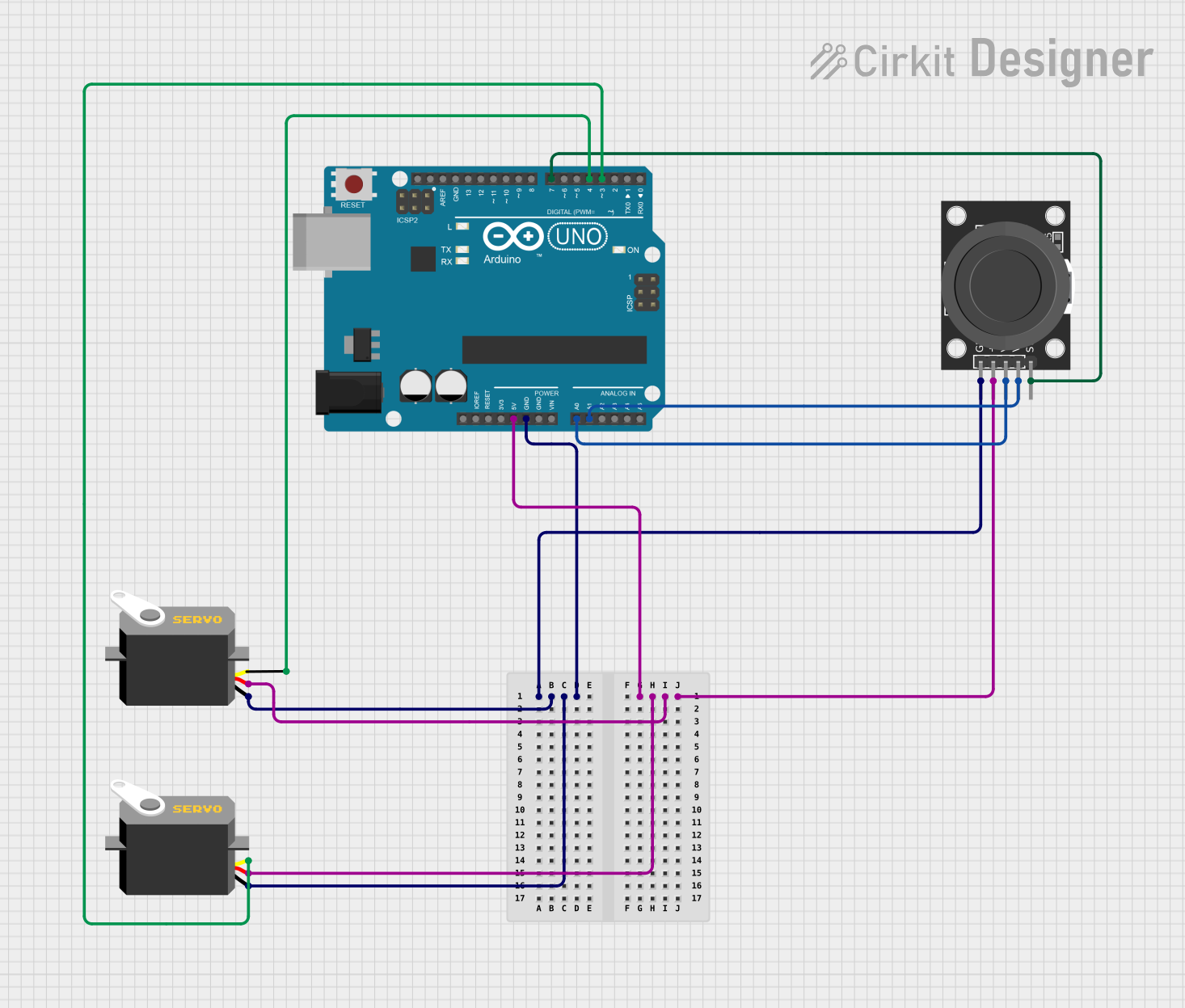
The circuit consists of an Arduino UNO microcontroller, two servo motors, and a KY-023 Dual Axis Joystick Module. The Arduino UNO serves as the central processing unit, controlling the servo motors based on the input from the joystick. The joystick provides two-axis control and a pushbutton switch, which can be used for user input. The servo motors are powered by the Arduino and receive pulse width modulation (PWM) signals to set their positions. The circuit is designed to allow for interactive control of the servo motors through the joystick's movements.
Component List
Arduino UNO
- Microcontroller board based on the ATmega328P
- Features digital I/O pins, analog input pins, and power supply pins
- Utilized for controlling the servo motors and reading inputs from the joystick
Servo Motor (x2)
- Electrically controlled device that can push or rotate an object with precision
- Consists of a motor coupled to a sensor for position feedback
- Controlled by sending a PWM signal through the pulse pin
KY-023 Dual Axis Joystick Module
- Two-axis joystick with a built-in pushbutton switch
- Outputs analog voltage proportional to the joystick's position
- Used for user input to control the servo motors
Wiring Details
Arduino UNO
- 5V pin connected to the VCC pins of both servo motors and the +5V pin of the joystick module
- GND pin connected to the GND pins of both servo motors and the GND pin of the joystick module
- A0 pin connected to the VRx pin of the joystick module (X-axis output)
- A1 pin connected to the VRy pin of the joystick module (Y-axis output)
- D7 pin connected to the SW pin of the joystick module (pushbutton switch)
- D4 pin connected to the pulse pin of one servo motor
- D3 pin connected to the pulse pin of the other servo motor
Servo Motor
- VCC pin connected to the 5V supply from the Arduino UNO
- GND pin connected to the ground of the Arduino UNO
- Pulse pin connected to a digital pin (D4 or D3) on the Arduino UNO for PWM control
KY-023 Dual Axis Joystick Module
- +5V pin connected to the 5V supply from the Arduino UNO
- GND pin connected to the ground of the Arduino UNO
- VRx pin connected to the A0 pin on the Arduino UNO (X-axis output)
- VRy pin connected to the A1 pin on the Arduino UNO (Y-axis output)
- SW pin connected to the D7 pin on the Arduino UNO (pushbutton switch)
Documented Code
Arduino UNO Code (sketch.ino)
void setup() {
  // put your setup code here, to run once:

}

void loop() {
  // put your main code here, to run repeatedly:

}
This code template provides the basic structure for the Arduino sketch. The setup() function is intended for initialization code that runs once, such as setting pin modes. The loop() function contains the main logic of the program, which runs repeatedly. The user will need to fill in these functions with code to read the joystick inputs, process them, and control the servo motors accordingly.
Additional Notes
- The provided code is a template and requires further implementation for functionality.
- The
documentation.txtfile is empty and does not contain any additional information.