
ESP32-Based Smart Irrigation System with Soil Moisture Sensing and Wi-Fi Control
View and Edit Project In Cirkit Designer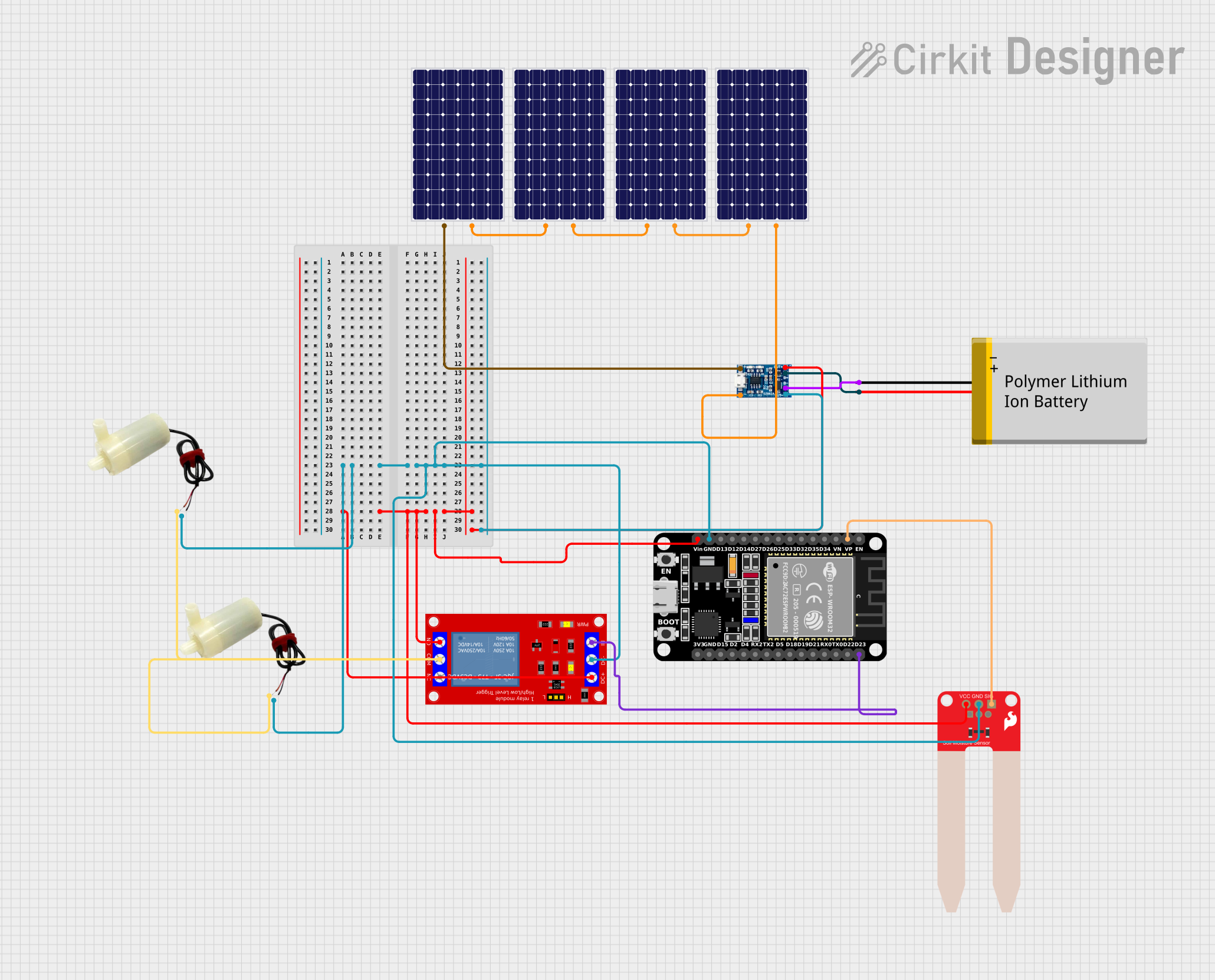
Smart Plant Irrigation System Documentation
Summary
The Smart Plant Irrigation System is designed to automatically water plants based on soil moisture levels. It utilizes an ESP32 microcontroller to monitor the soil moisture via a SparkFun Soil Moisture Sensor and control a 5V mini water pump through a 1 Channel 5V Relay Module. The system can be manually overridden through the Blynk mobile app. Power is supplied by solar panels charging a Polymer Lithium Ion Battery through a TP4056 Charging Module.
Component List
1 Channel 5V Relay Module
- Description: A relay module used to control high power devices.
- Pins: VCC+, VCC- (GND), IN, N.O., COM, N.C.
SparkFun Soil Moisture Sensor
- Description: A sensor that measures the moisture level in the soil.
- Pins: VCC, GND, SIG
5V Mini Water Pump
- Description: A small pump used for moving water.
- Pins: Positive pin, Negative pin
Solar Panel
- Description: A panel that converts solar energy into electrical power.
- Pins: +, -
Polymer Lithium Ion Battery - Generic
- Description: A rechargeable battery for power storage.
- Pins: GND, VCC
ESP32 (30 pin)
- Description: A microcontroller with Wi-Fi capabilities for controlling and monitoring the system.
- Pins: EN, VP, VN, D34, D35, D32, D33, D25, D26, D27, D14, D12, D13, GND, Vin, D23, D22, TX0, RX0, D21, D19, D18, D5, TX2, RX2, D4, D2, D15, 3V3
TP4056 Charging Module
- Description: A module used for charging the battery via the solar panels.
Wiring Details
1 Channel 5V Relay Module
- VCC+ connected to TP4056 Charging Module (Power)
- VCC- (GND) connected to GND of ESP32, Soil Moisture Sensor, Water Pumps, and TP4056 Charging Module
- IN connected to D23 of ESP32 (Control Signal)
- N.O. not connected
- COM connected to positive pins of Water Pumps
- N.C. not connected
SparkFun Soil Moisture Sensor
- VCC connected to TP4056 Charging Module (Power)
- GND connected to GND of ESP32, Relay Module, Water Pumps, and TP4056 Charging Module
- SIG connected to VP of ESP32 (Moisture Level Signal)
5V Mini Water Pump
- Positive pin connected to COM of Relay Module
- Negative pin connected to GND of ESP32, Relay Module, Soil Moisture Sensor, and TP4056 Charging Module
Solar Panel
- + connected to TP4056 Charging Module (Power Input)
- - connected to GND of TP4056 Charging Module
Polymer Lithium Ion Battery - Generic
- GND connected to GND of TP4056 Charging Module
- VCC connected to VCC of TP4056 Charging Module
ESP32 (30 pin)
- GND connected to GND of Relay Module, Soil Moisture Sensor, Water Pumps, and TP4056 Charging Module
- Vin connected to TP4056 Charging Module (Power)
- D23 connected to IN of Relay Module (Control Signal)
- VP connected to SIG of Soil Moisture Sensor (Moisture Level Signal)
TP4056 Charging Module
- Connected to Solar Panels, Polymer Lithium Ion Battery, ESP32, Relay Module, Soil Moisture Sensor, and Water Pumps for power management.
Documented Code
ESP32 Microcontroller Code
#define BLYNK_TEMPLATE_ID "TMPL3dNQsuofF"
#define BLYNK_TEMPLATE_NAME "smart plant"
#define BLYNK_AUTH_TOKEN "TT_GWt7M_Ok7mrsgwd4e-Jw_Wlk9Hc-F"

#define BLYNK_PRINT Serial

#include <WiFi.h>
#include <BlynkSimpleEsp32.h>

// Blynk auth token
char auth[] = BLYNK_AUTH_TOKEN;

// WiFi credentials
char ssid[] = "Your_SSID";
char pass[] = "Your_WIFI_Password";

// Pin configurations
const int relayPin = 23;             // Relay pin (connected to D23)
const int soilMoisturePin = 36;      // Soil moisture sensor pin (connected to VP)

// Thresholds
const int soilMoistureThreshold = 1500; // Soil moisture threshold

BlynkTimer timer;

// Function to read soil moisture
void checkSoilMoisture() {
  int soilMoisture = analogRead(soilMoisturePin);
  Blynk.virtualWrite(V4, soilMoisture); // Send soil moisture to Blynk

  // Automatic pump control based on soil moisture (water level)
  if (soilMoisture > soilMoistureThreshold) {
    digitalWrite(relayPin, LOW); // Turn on pump
    Blynk.virtualWrite(V2, "Pump ON");
    Blynk.logEvent("WaterLevel", "Water pump turned ON due to low water level."); // Log event for low water level
  } else {
    digitalWrite(relayPin, HIGH); // Turn off pump
    Blynk.virtualWrite(V2, "Pump OFF");
    Blynk.logEvent("WaterLevel", "Water pump turned OFF as water level is sufficient."); // Log event for sufficient water level
  }
}

// Blynk function to manually control the pump (virtual button)
BLYNK_WRITE(V3) {
  int pumpControl = param.asInt(); // Get value from Blynk app (1 or 0)

  if (pumpControl == 1) {
    digitalWrite(relayPin, LOW); // Turn on pump
    Blynk.virtualWrite(V2, "Pump ON");
    Blynk.logEvent("WaterLevel", "Water pump turned ON manually."); // Log event for manual pump ON
  } else {
    digitalWrite(relayPin, HIGH); // Turn off pump
    Blynk.virtualWrite(V2, "Pump OFF");
    Blynk.logEvent("WaterLevel", "Water pump turned OFF manually."); // Log event for manual pump OFF
  }
}

void setup() {
  // Start serial communication
  Serial.begin(115200);

  // Setup relay pin
  pinMode(relayPin, OUTPUT);
  digitalWrite(relayPin, HIGH); // Turn off pump initially

  // Setup soil moisture sensor pin
  pinMode(soilMoisturePin, INPUT);

  // Connect to WiFi and Blynk
  Blynk.begin(auth, ssid, pass);

  // Setup timers to check soil moisture every 5 seconds
  timer.setInterval(5000L, checkSoilMoisture);  // Check soil moisture
}

void loop() {
  // Run Blynk
  Blynk.run();

  // Run the timer
  timer.run();
}
TP4056 Charging Module Code
void setup() {
  // put your setup code here, to run once:

}

void loop() {
  // put your main code here, to run repeatedly:

}
Note: The TP4056 Charging Module code is empty as it does not require programming for its basic charging function.