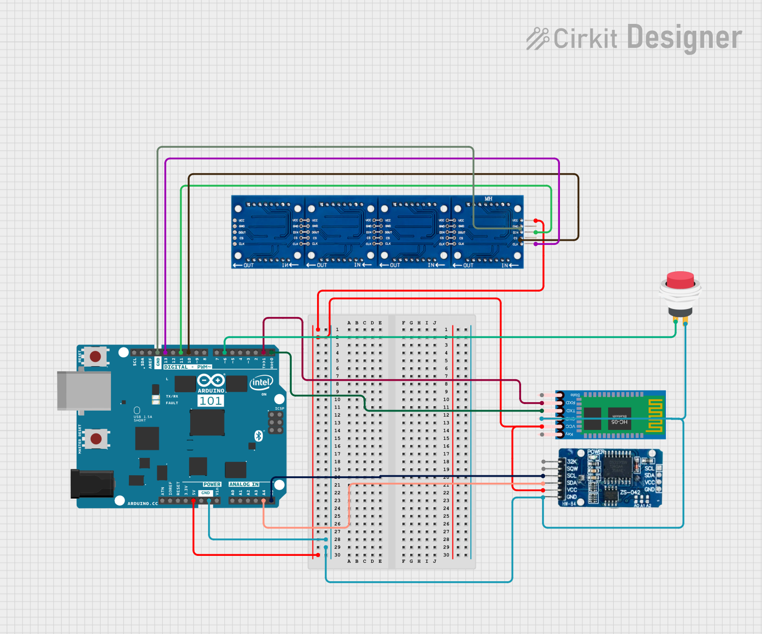
Arduino 101 Based Bluetooth-Controlled Dot Matrix Display with RTC Integration

Circuit Documentation
Summary
The circuit in question is designed to interface an Arduino 101 microcontroller with a dot matrix LED display, a Real-Time Clock (RTC) module DS3231, a 2Pin Push Switch, and an HC-05 Bluetooth Module. The Arduino 101 serves as the central processing unit, controlling the LED display, maintaining time with the RTC, and communicating wirelessly via the Bluetooth module. The push switch is used as an input device, likely for user interaction.
Component List
Arduino 101
- Description: A microcontroller board based on the Intel Curie Module, designed for building IoT projects.
- Pins: A5/SCL, A4/SDA, AREF, GND, D13/SCK, D12/MISO, D11 PWM/MOSI, D10 PWM/SS, D9 PWM, D8, D7, D6 PWM, D5 PWM, D4, D3 PWM, D2, D1/TX, D0/RX, AIN, ioref, RESET, 3V3, 5V, VIN, A0, A1, A2, A3, ICSP MISO, ICSP SCK, ICSP MOSI.
Dot Matrix LED
- Description: A display composed of an array of LEDs that can be individually controlled to display characters, symbols, or animations.
- Pins: gnd, DIN, vcc, CLK, CS.
2Pin Push Switch
- Description: A simple push-button switch that allows current to flow when pressed.
- Pins: Input +, Output +.
RTC DS3231
- Description: A highly accurate I2C real-time clock with an integrated temperature-compensated crystal oscillator (TCXO) and crystal.
- Pins: 32K, SQW, SCL, SDA, VCC, GND.
HC-05 Bluetooth Module
- Description: A widely used Bluetooth module for wireless communication.
- Pins: Key, VCC, TXD, RXD, State, GND.
Wiring Details
Arduino 101
- 5V connected to VCC of Dot Matrix LED, RTC DS3231, HC-05 Bluetooth Module.
- GND connected to GND of Dot Matrix LED, RTC DS3231, 2Pin Push Switch, HC-05 Bluetooth Module.
- A5/SCL connected to SCL of RTC DS3231.
- A4/SDA connected to SDA of RTC DS3231.
- D13/SCK connected to CLK of Dot Matrix LED.
- D11 PWM/MOSI connected to DIN of Dot Matrix LED.
- D10 PWM/SS connected to CS of Dot Matrix LED.
- D6 PWM connected to Input + of 2Pin Push Switch.
- D1/TX connected to RXD of HC-05 Bluetooth Module.
- D0/RX connected to TXD of HC-05 Bluetooth Module.
Dot Matrix LED
- vcc connected to 5V of Arduino 101.
- gnd connected to GND of Arduino 101.
- DIN connected to D11 PWM/MOSI of Arduino 101.
- CLK connected to D13/SCK of Arduino 101.
- CS connected to D10 PWM/SS of Arduino 101.
2Pin Push Switch
- Input + connected to D6 PWM of Arduino 101.
- Output + connected to GND of Arduino 101.
RTC DS3231
- VCC connected to 5V of Arduino 101.
- GND connected to GND of Arduino 101.
- SCL connected to A5/SCL of Arduino 101.
- SDA connected to A4/SDA of Arduino 101.
HC-05 Bluetooth Module
- VCC connected to 5V of Arduino 101.
- GND connected to GND of Arduino 101.
- TXD connected to D0/RX of Arduino 101.
- RXD connected to D1/TX of Arduino 101.
Code Documentation
No code has been provided for the microcontrollers in the circuit. To fully utilize the hardware, embedded code should be written and uploaded to the Arduino 101 microcontroller. The code should handle the initialization and communication with the RTC DS3231, the Dot Matrix LED display, and the HC-05 Bluetooth Module. It should also include debouncing for the 2Pin Push Switch and appropriate interrupt service routines or polling mechanisms to detect button presses.