
Arduino Nano-Based Multi-Zone Soil Moisture Monitor with OLED Display
View and Edit Project In Cirkit Designer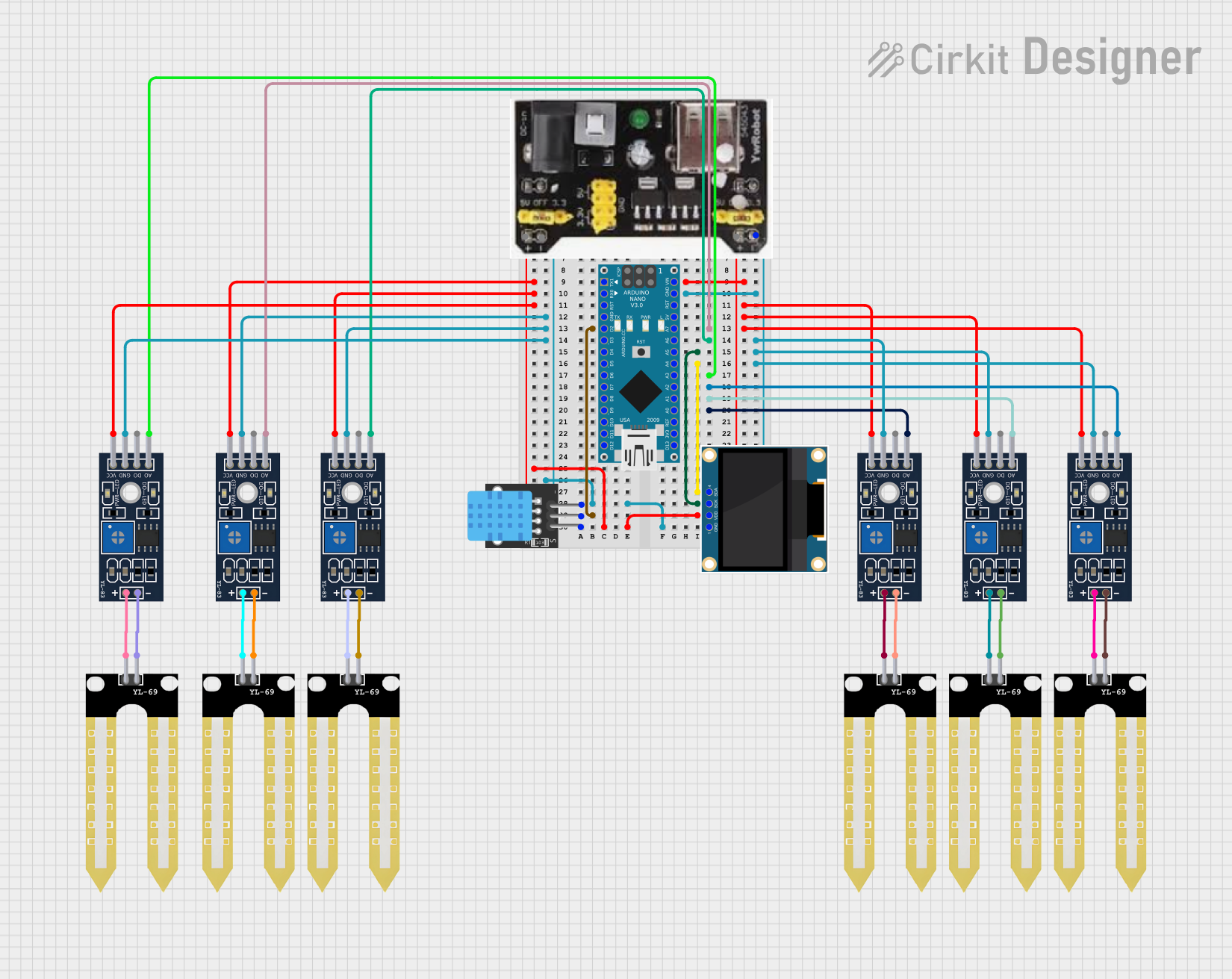
Circuit Documentation
Summary
This circuit is designed to interface various sensors and an OLED display with an Arduino Nano microcontroller. The sensors include multiple YL-69 soil moisture probes and YL-83 raindrop sensors, which are interfaced with LM393 comparator modules. The circuit also includes a KY-015 DHT11 temperature and humidity sensor and a 0.96" OLED display for output. The MB102 Breadboard Power Supply Module provides power to the circuit. The Arduino Nano serves as the central processing unit, reading sensor data and controlling the OLED display.
Component List
MB102 Breadboard Power Supply Module 3.3V/5V
- Provides selectable 3.3V or 5V power to the circuit.
- Pins: GND, 3.3V, 5V
YL-69 Sonda (Soil Moisture Sensor)
- Detects the moisture level in the soil.
- Pins: +, -
0.96" OLED Display
- Displays information such as sensor readings.
- Pins: GND, VDD, SCK, SDA
YL-83 Module LM393 (Raindrop Sensor)
- Detects raindrops or water flow using a comparator.
- Pins: A0, D0, GND, VCC, -, +
Arduino Nano
- Microcontroller for processing and controlling the circuit.
- Pins: D1/TX, D0/RX, RESET, GND, D2, D3, D4, D5, D6, D7, D8, D9, D10, D11/MOSI, D12/MISO, VIN, 5V, A7, A6, A5, A4, A3, A2, A1, A0, AREF, 3V3, D13/SCK
KY-015 DHT11 (Temperature and Humidity Sensor)
- Measures ambient temperature and humidity.
- Pins: 5V, S, GND
Wiring Details
MB102 Breadboard Power Supply Module 3.3V/5V
- GND connected to Arduino Nano GND.
- 5V output used to power the circuit components.
YL-69 Sonda (Soil Moisture Sensor)
- Multiple instances, each connected to a corresponding YL-83 Module LM393:
-
- pin connected to + pin of YL-83 Module LM393.
-
- pin connected to - pin of YL-83 Module LM393.
-
0.96" OLED Display
- GND connected to Arduino Nano GND.
- VDD connected to KY-015 DHT11 5V.
- SCK connected to Arduino Nano A5.
- SDA connected to Arduino Nano A4.
YL-83 Module LM393 (Raindrop Sensor)
- Multiple instances, each with the following connections:
- A0 connected to a unique analog input on the Arduino Nano (A0, A1, A2, A3, A6, A7).
- D0 not used in this configuration.
- GND connected to Arduino Nano GND.
- VCC connected to Arduino Nano VIN.
-
- pin connected to + pin of corresponding YL-69 Sonda.
-
- pin connected to - pin of corresponding YL-69 Sonda.
Arduino Nano
- VIN connected to VCC of all YL-83 Module LM393.
- GND connected to GND of all components.
- Digital and analog pins connected to various sensors and the OLED display as detailed above.
KY-015 DHT11 (Temperature and Humidity Sensor)
- 5V connected to 0.96" OLED VDD.
- S connected to Arduino Nano D2.
- GND connected to Arduino Nano GND.
Documented Code
Arduino Nano Code (sketch.ino)
void setup() {
  // put your setup code here, to run once:

}

void loop() {
  // put your main code here, to run repeatedly:

}
This is the basic structure of an Arduino sketch, with setup() function to initialize settings and loop() function to contain the main logic that will run continuously. The actual implementation details will depend on the specific requirements of the circuit's functionality, such as reading sensor data and updating the OLED display.