
Circuit Documentation
Summary of the Circuit
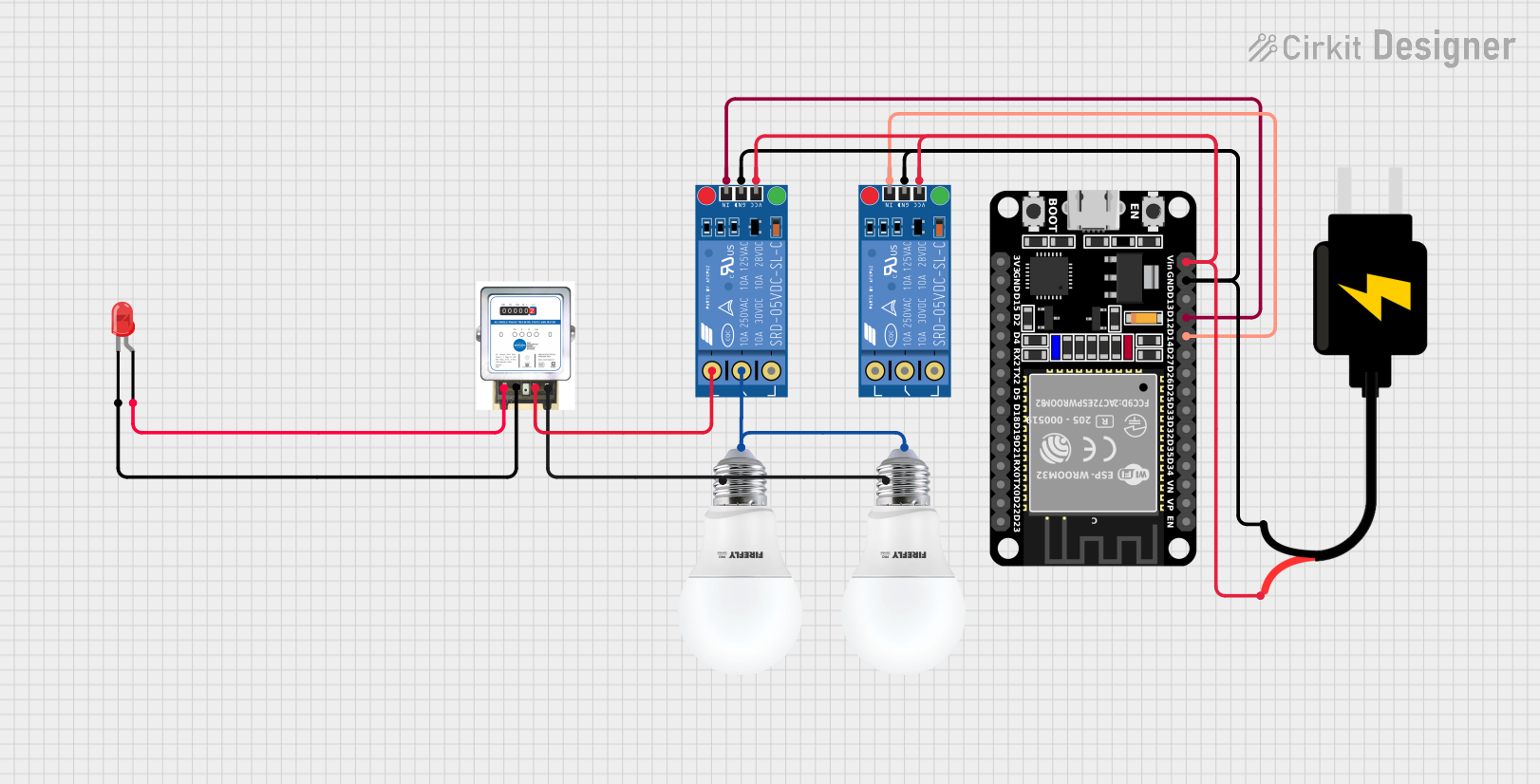
This circuit appears to be designed to control two bulbs and an analog meter using two KF-301 relays, which are in turn controlled by an ESP32 microcontroller. The ESP32 is powered by a DC Source of 5V. The relays are used to switch the bulbs on and off, and the analog meter is connected to a red LED, possibly for indication purposes. The ESP32 has two of its GPIO pins connected to the signal pins of the relays, allowing it to control the state of the relays.
Component List
Analog Meter
- Description: A device used to display a measurement in an analog form.
- Pins: in +, IN -, Out +, Out -
KF-301 Relay
- Description: An electromechanical switch used to control a high power or high voltage circuit with a low power signal.
- Pins: signal, power, ground, NC (Normally Closed), C (Common), NO (Normally Open)
Bulb
- Description: An electric light source.
- Pins: +, -
ESP32 (30 pin)
- Description: A microcontroller with Wi-Fi and Bluetooth capabilities.
- Pins: EN, VP, VN, D34, D35, D32, D33, D25, D26, D27, D14, D12, D13, GND, Vin, D23, D22, TX0, RX0, D21, D19, D18, D5, TX2, RX2, D4, D2, D15, 3V3
LED: Two Pin (red)
- Description: A red light-emitting diode.
- Pins: cathode, anode
DC Source 5V
- Description: A power supply that provides a 5V output.
- Pins: VCC, GND
Wiring Details
Analog Meter
- in +: Connected to the anode of the red LED.
- IN -: Connected to the cathode of the red LED.
- Out +: Connected to the NO (Normally Open) pin of one of the KF-301 Relays.
- Out -: Connected to the negative pins of both bulbs.
KF-301 Relay (First Instance)
- signal: Controlled by the D12 pin of the ESP32.
- power: Connected to the VCC of the DC Source 5V.
- ground: Connected to the GND of the DC Source 5V.
- NC: Not connected in this circuit.
- C: Connected to the positive pins of both bulbs.
- NO: Connected to the Out + of the Analog Meter.
KF-301 Relay (Second Instance)
- signal: Controlled by the D14 pin of the ESP32.
- power: Connected to the VCC of the DC Source 5V.
- ground: Connected to the GND of the DC Source 5V.
- NC: Not connected in this circuit.
- C: Not connected in this circuit.
- NO: Not connected in this circuit.
Bulb (First Instance)
- +: Connected to the C (Common) pin of the first KF-301 Relay.
- -: Connected to the Out - of the Analog Meter.
Bulb (Second Instance)
- +: Connected to the C (Common) pin of the first KF-301 Relay.
- -: Connected to the Out - of the Analog Meter.
ESP32 (30 pin)
- D12: Controls the signal pin of the first KF-301 Relay.
- D14: Controls the signal pin of the second KF-301 Relay.
- Vin: Connected to the VCC of the DC Source 5V.
- GND: Connected to the GND of the DC Source 5V.
- Other pins are not used in this circuit.
LED: Two Pin (red)
- anode: Connected to the in + of the Analog Meter.
- cathode: Connected to the IN - of the Analog Meter.
DC Source 5V
- VCC: Provides power to the ESP32 and both KF-301 Relays.
- GND: Common ground for the ESP32 and both KF-301 Relays.
Documented Code
No code was provided for the microcontroller. Therefore, this section is not applicable for the current documentation. If code is provided at a later stage, it should be documented here, including descriptions of what each part of the code does, particularly how it interfaces with the relays and other components in the circuit.