Arduino UNO Controlled Environment Monitoring System with OLED Display and Motorized Alert Mechanism
Circuit Documentation
Summary
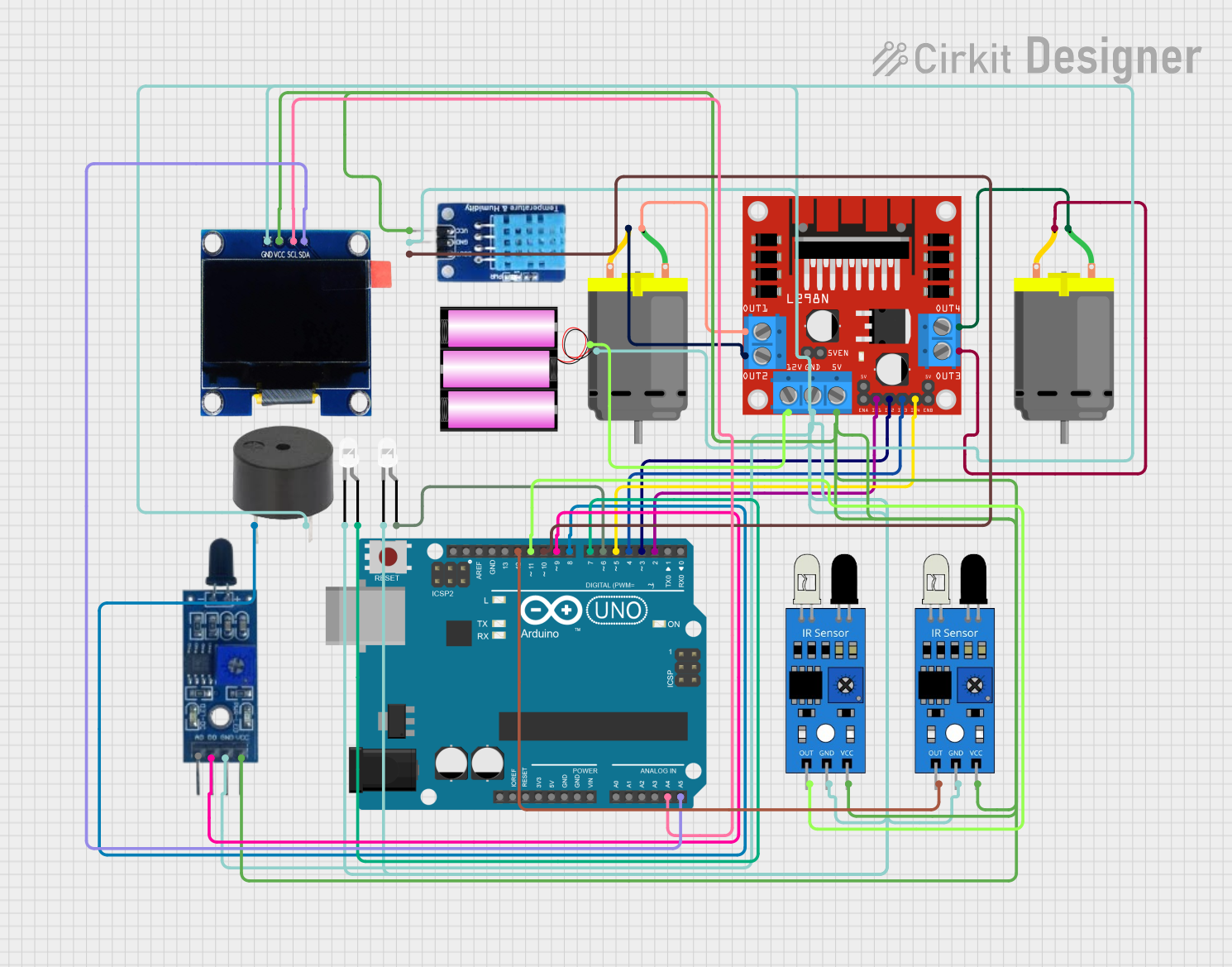
The circuit in question is designed to interface an Arduino UNO with a variety of sensors, actuators, and a display. The primary components include an OLED display for output, a DHT11 sensor for temperature and humidity measurements, IR sensors for object detection, a flame sensor for fire detection, LEDs for visual indication, a buzzer for audio alerts, and a L298N motor driver to control two DC motors. The Arduino UNO serves as the central processing unit, running embedded code to interact with the connected components, process sensor data, and control the actuators based on the sensor inputs.
Component List
Arduino UNO
- Microcontroller board based on the ATmega328P
- Used as the main controller for the circuit
L298N DC Motor Driver
- Module for controlling up to two DC motors
- Provides the ability to drive the motors in both directions
DC Motors (x2)
- Converts electrical energy into mechanical motion
- Connected to the L298N motor driver
Buzzer
- Emits an audible alert when activated
- Used for audio notifications in the circuit
LEDs (x2, white)
- Provides visual indication
- Used to signal various states in the circuit
Flame Sensor
- Detects the presence of a flame or fire
- Used for fire detection and safety measures
DHT11
- Sensor for measuring temperature and humidity
- Provides environmental data to the Arduino UNO
OLED 1.3" Display
- Screen for displaying text and graphics
- Used to output sensor readings and status information
Battery (12V)
- Power source for the motor driver and motors
IR Sensors (x2)
- Detects proximity or presence of objects
- Used for object detection and avoidance
Wiring Details
OLED 1.3" Display
SCLconnected to Arduino UNOA4SDAconnected to Arduino UNOA5GNDconnected to common groundVCCconnected to 5V power supply
IR Sensors
outof first IR sensor connected to Arduino UNOD12outof second IR sensor connected to Arduino UNOD11gndconnected to common groundvccconnected to 5V power supply
DHT11
DATAconnected to Arduino UNOD10GNDconnected to common groundVCCconnected to 5V power supply
Flame Sensor
D0connected to Arduino UNOD9GNDconnected to common groundVCCconnected to 5V power supply
Buzzer
PINconnected to Arduino UNOD8GNDconnected to common ground
LEDs
anodeof first LED connected to Arduino UNOD7anodeof second LED connected to Arduino UNOD6cathodeconnected to common ground
L298N DC Motor Driver
IN1connected to Arduino UNOD2IN2connected to Arduino UNOD3IN3connected to Arduino UNOD4IN4connected to Arduino UNOD5OUT1connected to first DC Motorpin 1OUT2connected to first DC Motorpin 2OUT3connected to second DC Motorpin 2OUT4connected to second DC Motorpin 112Vconnected to 12V battery+GNDconnected to common ground5Vconnected to 5V power supply
Battery (12V)
+connected to L298N DC motor driver12V-connected to common ground
Documented Code
#include <Wire.h>
#include <Adafruit_GFX.h>
#include <Adafruit_SSD1306.h>

// OLED display settings
#define SCREEN_WIDTH 128
#define SCREEN_HEIGHT 64
#define OLED_RESET -1
Adafruit_SSD1306 display(SCREEN_WIDTH, SCREEN_HEIGHT, &Wire, OLED_RESET);

// DHT11 settings
#define DHTPIN 10
#define DHTTYPE DHT11
DHT dht(DHTPIN, DHTTYPE);

// Flame sensor pin
#define FLAME_SENSOR_PIN 9

// Buzzer pin
#define BUZZER_PIN 8

// LED pins
#define LED1_PIN 7
#define LED2_PIN 6

// L298N motor driver pins
#define IN1_PIN 2
#define IN2_PIN 3
#define IN3_PIN 4
#define IN4_PIN 5

// IR sensor pins
#define IR_SENSOR1_PIN 11
#define IR_SENSOR2_PIN 12

void setup() {
  // Initialize serial communication
  Serial.begin(9600);

  // Initialize OLED display
  if (!display.begin(SSD1306_I2C_ADDRESS, OLED_RESET)) {
    Serial.println(F("SSD1306 allocation failed"));
    for (;;);
  }
  display.display();
  delay(2000);
  display.clearDisplay();

  // Initialize DHT11 sensor
  dht.begin();

  // Initialize flame sensor pin
  pinMode(FLAME_SENSOR_PIN, INPUT);

  // Initialize buzzer pin
  pinMode(BUZZER_PIN, OUTPUT);

  // Initialize LED pins
  pinMode(LED1_PIN, OUTPUT);
  pinMode(LED2_PIN, OUTPUT);

  // Initialize motor driver pins
  pinMode(IN1_PIN, OUTPUT);
  pinMode(IN2_PIN, OUTPUT);
  pinMode(IN3_PIN, OUTPUT);
  pinMode(IN4_PIN, OUTPUT);

  // Initialize IR sensor pins
  pinMode(IR_SENSOR1_PIN, INPUT);
  pinMode(IR_SENSOR2_PIN, INPUT);
}

void loop() {
  // Read DHT11 sensor data
  float humidity = dht.readHumidity();
  float temperature = dht.readTemperature();

  // Read flame sensor data
  int flameSensorValue = digitalRead(FLAME_SENSOR_PIN);

  // Read IR sensor data
  int irSensor1Value = digitalRead(IR_SENSOR1_PIN);
  int irSensor2Value = digitalRead(IR_SENSOR2_PIN);

  // Display data on OLED
  display.clearDisplay();
  display.setTextSize(1);
  display.setTextColor(SSD1306_WHITE);
  display.setCursor(0, 0);
  display.print("Temp: ");
  display.print(temperature);
  display.print(" C");
  display.setCursor(0, 10);
  display.print("Humidity: ");
  display.print(humidity);
  display.print(" %");
  display.setCursor(0, 20);
  display.print("Flame: ");
  display.print(flameSensorValue ? "No" : "Yes");
  display.setCursor(0, 30);
  display.print("IR1: ");
  display.print(irSensor1Value ? "No" : "Yes");
  display.setCursor(0, 40);
  display.print("IR2: ");
  display.print(irSensor2Value ? "No" : "Yes");
  display.display();

  // Control buzzer based on flame sensor
  if (flameSensorValue == LOW) {
    digitalWrite(BUZZER_PIN, HIGH);
  } else {
    digitalWrite(BUZZER_PIN, LOW);
  }

  // Control LEDs based on IR sensors
  digitalWrite(LED1_PIN, irSensor1Value == LOW ? HIGH : LOW);
  digitalWrite(LED2_PIN, irSensor2Value == LOW ? HIGH : LOW);

  // Control motors (example: forward motion)
  digitalWrite(IN1_PIN, HIGH);
  digitalWrite(IN2_PIN, LOW);
  digitalWrite(IN3_PIN, HIGH);
  digitalWrite(IN4_PIN, LOW);

  delay(1000);
}
How to Upload Code
To upload the code to your Arduino UNO, follow these steps:
Install the Arduino IDE:
- If you haven't already, download and install the Arduino IDE from the official Arduino website.
Connect the Arduino UNO:
- Connect your Arduino UNO to your computer using a USB cable.
Open the Arduino IDE:
- Launch the Arduino IDE on your computer.
Create a New Sketch:
- Go to File > New to create a new sketch.
Copy and Paste the Code:
- Copy the provided code and paste it into the new sketch window in the Arduino IDE.
Install Required Libraries:
- The code uses the Adafruit_GFX and Adafruit_SSD1306 libraries for the OLED display and the DHT library for the DHT11 sensor. You need to install these libraries if you haven't already.
- Go to Sketch > Include Library > Manage Libraries...
- In the Library Manager, search for Adafruit GFX and Adafruit SSD1306, then click Install for both.
- Similarly, search for DHT sensor library and click Install.
Select the Board and Port:
- Go to Tools > Board and select Arduino/Genuino UNO.
- Go to Tools > Port and select the port to which your Arduino UNO is connected (e.g., COM3 on Windows or /dev/tty.usbmodem14101 on macOS).
Upload the Code:
- Click the Upload button (right arrow icon) in the Arduino IDE toolbar.