
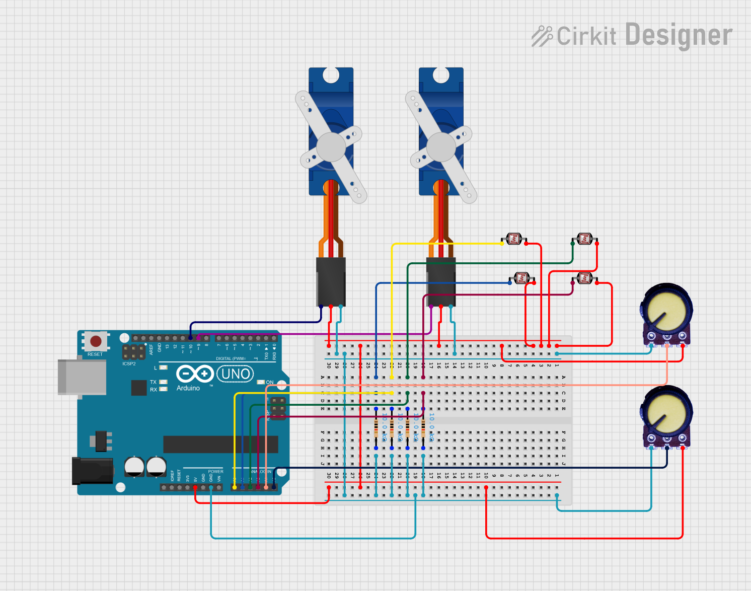
Circuit Documentation
Summary
This circuit involves an Arduino UNO microcontroller interfacing with multiple resistors, potentiometers, servos, and photocells (LDRs). The circuit is designed to read analog signals from the photocells and potentiometers, and control the servos based on these inputs.
Component List
Arduino UNO
- Description: A microcontroller board based on the ATmega328P.
- Pins: UNUSED, IOREF, Reset, 3.3V, 5V, GND, Vin, A0, A1, A2, A3, A4, A5, SCL, SDA, AREF, D13, D12, D11, D10, D9, D8, D7, D6, D5, D4, D3, D2, D1, D0
Resistor (10k Ohms)
- Description: A resistor with a resistance of 10k Ohms.
- Pins: pin1, pin2
Potentiometer
- Description: A variable resistor with three terminals.
- Pins: GND, Output, VCC
Tower Pro SG90 Servo
- Description: A small servo motor.
- Pins: Signal, +5V, GND
Photocell (LDR)
- Description: A light-dependent resistor.
- Pins: pin 0, pin 1
Wiring Details
Arduino UNO
- A0: Connected to pin1 of a 10k Ohm resistor and pin 0 of a Photocell (LDR).
- A1: Connected to pin1 of a 10k Ohm resistor and pin 0 of a Photocell (LDR).
- A2: Connected to pin1 of a 10k Ohm resistor and pin 0 of a Photocell (LDR).
- A3: Connected to pin1 of a 10k Ohm resistor and pin 0 of a Photocell (LDR).
- A4: Connected to Output of a Potentiometer.
- A5: Connected to Output of a Potentiometer.
- D9: Connected to Signal of a Tower Pro SG90 servo.
- D10: Connected to Signal of a Tower Pro SG90 servo.
- 5V: Connected to VCC of two Potentiometers, +5V of two Tower Pro SG90 servos, and pin 1 of four Photocells (LDRs).
- GND: Connected to GND of two Potentiometers, GND of two Tower Pro SG90 servos, and pin2 of four 10k Ohm resistors.
Resistor (10k Ohms)
- pin1: Connected to A0, A1, A2, and A3 of Arduino UNO.
- pin2: Connected to GND of Arduino UNO.
Potentiometer
- GND: Connected to GND of Arduino UNO.
- Output: Connected to A4 and A5 of Arduino UNO.
- VCC: Connected to 5V of Arduino UNO.
Tower Pro SG90 Servo
- Signal: Connected to D9 and D10 of Arduino UNO.
- +5V: Connected to 5V of Arduino UNO.
- GND: Connected to GND of Arduino UNO.
Photocell (LDR)
- pin 0: Connected to A0, A1, A2, and A3 of Arduino UNO.
- pin 1: Connected to 5V of Arduino UNO.
Documented Code
sketch.ino
void setup() {
  // put your setup code here, to run once:

}

void loop() {
  // put your main code here, to run repeatedly:

}
documentation.txt
This documentation provides a comprehensive overview of the circuit, including a summary, detailed component list, wiring details, and the code used in the microcontroller.