Cirkit Designer
Your all-in-one circuit design IDE
Home /
Project Documentation
ESP32-Based Smart Temperature-Controlled Fan with OLED Display

Circuit Documentation
Summary
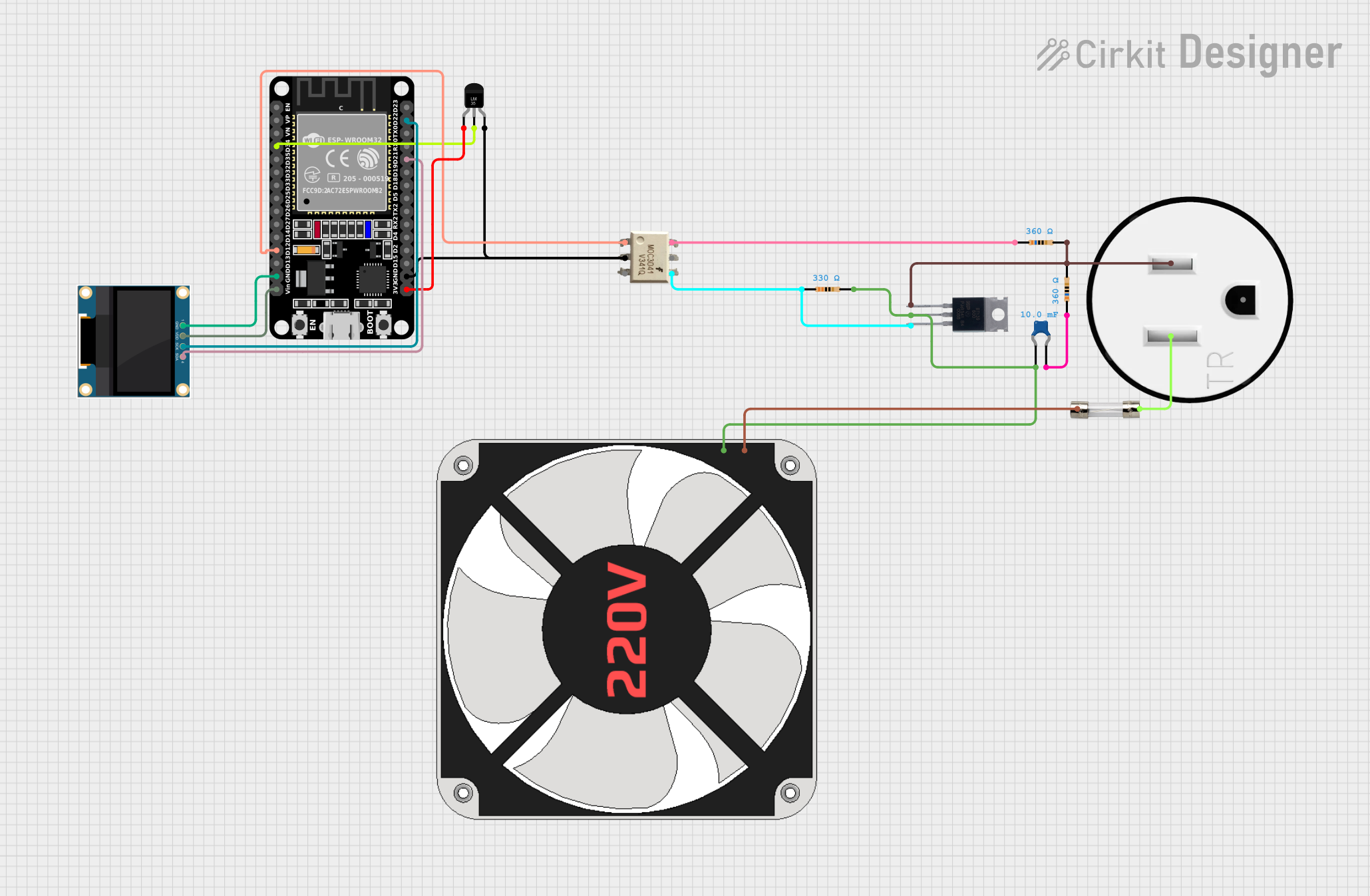
This circuit is designed to control a 220V fan using an ESP32 microcontroller based on temperature readings from an LM35 temperature sensor. The fan's speed is regulated through phase angle control implemented with a MOC3041 optoisolator and a BT139 triac. The system also includes a 0.96" OLED display to provide real-time feedback on the temperature and fan speed. Safety features include a 5A fuse in series with the 120V outlet to protect against overcurrent conditions. The circuit is powered by the same 120V outlet, with resistors and a ceramic capacitor forming a snubber circuit for the triac.
Component List
- ESP32 (30 pin): A microcontroller with WiFi and Bluetooth capabilities, used for processing sensor data and controlling the fan and OLED display.
- 0.96" OLED: A small display connected via I2C to the ESP32, used to show temperature and fan speed.
- 120V Outlet: Provides AC power to the circuit and the fan.
- MOC3041: An optoisolator used to safely trigger the triac for controlling the fan speed.
- Temperature Sensor (LM35): Measures the ambient temperature and provides an analog output proportional to the temperature.
- BT139 600: A triac used as a switch to control the power delivered to the fan.
- 220V Fan: The load in the circuit, whose speed is controlled based on the temperature reading.
- Resistors: Three resistors with different resistance values (360 Ohms, 330 Ohms, 360 Ohms) used for biasing and current limiting purposes.
- Ceramic Capacitor: A 0.01 Farad capacitor, part of the snubber circuit for the triac.
- 5A Fuse: Provides overcurrent protection for the circuit.
Wiring Details
ESP32 (30 pin)
EN,VP,VN,D35,D32,D33,D25,D26,D27,D14,TX0,RX0,D19,D18,D5,TX2,RX2,D4,D2,D15: Not connected.D34: Connected to theVoutpin of the Temperature Sensor (LM35).D12: Connected to theANODEpin of the MOC3041.D13: Not connected (presumably used for zero-cross detection).GND: Common ground with the OLED, MOC3041, and Temperature Sensor (LM35).Vin: Connected to theVDDpin of the 0.96" OLED.D23,D22: Connected to theSCKandSDApins of the 0.96" OLED for I2C communication.D21: Not connected in the net list but presumably used for I2C communication with the OLED.3V3: Connected to the+Vspin of the Temperature Sensor (LM35).
0.96" OLED
GND: Connected to theGNDpin of the ESP32.VDD: Connected to theVinpin of the ESP32.SCK: Connected to theD22pin of the ESP32.SDA: Connected to theD21pin of the ESP32.
120V Outlet
AC Neutral: Connected to theoutputpin of the 5A Fuse.AC Hot: Connected to thepin2of the 360 Ohms Resistor.GND: Not connected in the net list.
MOC3041
TRIAC1: Connected to thepin1of the 360 Ohms Resistor.NC: Not connected.TRIAC2: Connected to theGATEpin of the BT139 600 andpin1of the 330 Ohms Resistor.CATHODE: Connected to theGNDpin of the ESP32.ANODE: Connected to theD12pin of the ESP32.
Temperature Sensor (LM35)
+Vs: Connected to the3V3pin of the ESP32.Vout: Connected to theD34pin of the ESP32.GND: Connected to theGNDpin of the ESP32.
BT139 600
MT1: Connected to theAC Hotpin of the 120V Outlet.MT2: Connected to theLpin of the 220V Fan andpin0of the Ceramic Capacitor.GATE: Connected to theTRIAC2pin of the MOC3041 andpin1of the 330 Ohms Resistor.
220V Fan
N: Connected to theinputpin of the 5A Fuse.L: Connected to theMT2pin of the BT139 600.
Resistors
- 360 Ohms Resistor: One pin connected to the
AC Hotpin of the 120V Outlet, the other pin connected to theTRIAC1pin of the MOC3041. - 330 Ohms Resistor: One pin connected to the
GATEpin of the BT139 600, the other pin connected to theTRIAC2pin of the MOC3041 andpin0of the Ceramic Capacitor. - Another 360 Ohms Resistor: One pin connected to the
pin1of the Ceramic Capacitor, the other pin not connected in the net list.
Ceramic Capacitor
- One pin connected to the
MT2pin of the BT139 600 andpin2of the 330 Ohms Resistor. - The other pin connected to the
pin1of the 360 Ohms Resistor.
5A Fuse
input: Connected to theNpin of the 220V Fan.output: Connected to theAC Neutralpin of the 120V Outlet.
Documented Code
#include <Wire.h>
#include <Adafruit_GFX.h>
#include <Adafruit_SSD1306.h>

#define SCREEN_WIDTH 128  // OLED display width, in pixels
#define SCREEN_HEIGHT 64  // OLED display height, in pixels

// Declaration for an SSD1306 display connected to I2C (SDA, SCL pins)
#define OLED_RESET -1  // Reset pin (or -1 if sharing Arduino reset pin)
Adafruit_SSD1306 display(SCREEN_WIDTH, SCREEN_HEIGHT, &Wire, OLED_RESET);

#define LM35_PIN 34          // ESP32 analog input pin connected to LM35
#define TRIAC_PIN 12         // Pin controlling the TRIAC (GPIO 12)
#define ZERO_CROSS_PIN 13    // Pin connected to zero-cross detector (GPIO 13)
#define FAN_MAX_DELAY 8333   // Max delay in microseconds (100% off at 60Hz)

// Baseline temperature in °C (adjust this to your desired baseline)
float baselineTemp = 20.0;
int delayTime = 0;  // Delay for phase angle control

void IRAM_ATTR zeroCrossDetected() {
  delayMicroseconds(delayTime);
  digitalWrite(TRIAC_PIN, HIGH);  // Fire the TRIAC
  delayMicroseconds(10);          // Keep TRIAC on for a few microseconds
  digitalWrite(TRIAC_PIN, LOW);   // Turn off the TRIAC
}

void setup() {
  pinMode(TRIAC_PIN, OUTPUT);
  pinMode(ZERO_CROSS_PIN, INPUT);

  // Attach interrupt for zero-cross detection
  attachInterrupt(digitalPinToInterrupt(ZERO_CROSS_PIN), zeroCrossDetected, RISING);

  Serial.begin(115200);  // ESP32 operates faster, so use a higher baud rate

  // Initialize the OLED display
  if (!display.begin(SSD1306_SWITCHCAPVCC, 0x3C)) {  // Address 0x3C for most OLEDs
    Serial.println(F("SSD1306 allocation failed"));
    for (;;);  // Don't proceed, loop forever
  }
  display.clearDisplay();  // Clear the buffer
  display.setTextSize(4);  // Set text size (increase for bigger text)
  display.setTextColor(SSD1306_WHITE);  // Set text color

  delay(2000);  // Give display some time to initialize
}

void loop() {
  int sensorValue = analogRead(LM35_PIN);  // Read analog value from LM35

  // Convert the analog value to temperature in Celsius
  // LM35 outputs 10mV per degree Celsius, powered at 5V
  float voltage = sensorValue * (5.0 / 4095.0);  // Convert analog reading to voltage at 5V
  int currentTemp = (int)(voltage * 100);  // Convert voltage to temperature in Celsius as whole number

  // Display the temperature in the Serial Monitor
  Serial.print("Current Temp: ");
  Serial.println(currentTemp);

  // Display the temperature on the OLED
  display.clearDisplay();