
Raspberry Pi 5-Based Dual Ultrasonic Distance Measurement System
View and Edit Project In Cirkit Designer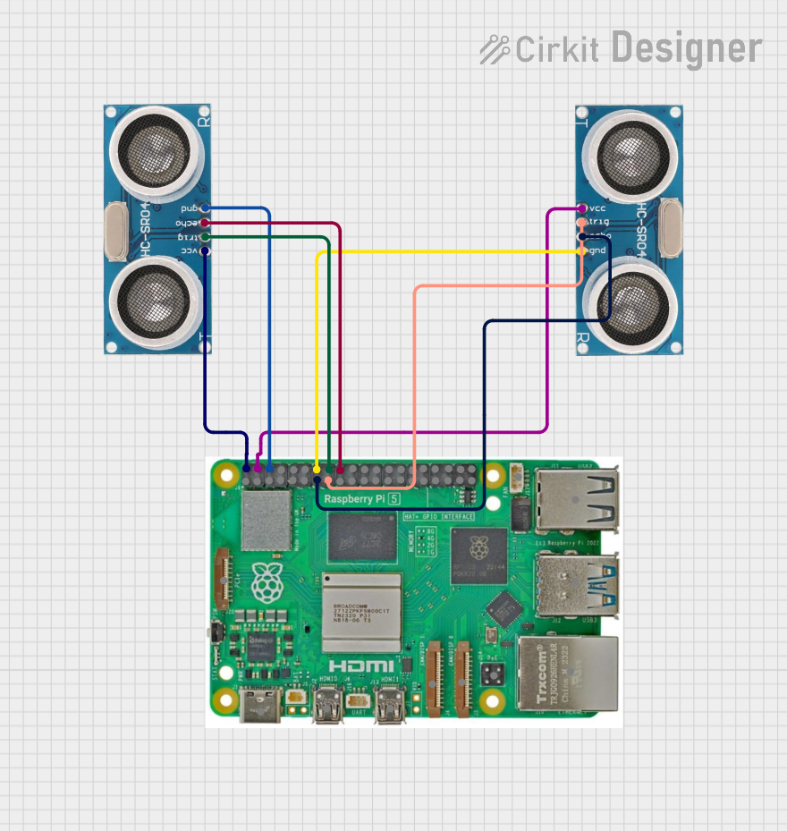
Circuit Documentation
Summary of the Circuit
This circuit integrates a Raspberry Pi 5 with two Ultrasonic Sensors. The Raspberry Pi 5 serves as the central processing unit, providing power and GPIO connections to the Ultrasonic Sensors. The sensors are used to measure distances by emitting ultrasonic waves and measuring the time it takes for the echoes to return. The circuit is designed to operate with a 5V power supply from the Raspberry Pi 5, which is common for many low-power sensors and peripherals.
Component List
Raspberry Pi 5
- Description: A powerful microcomputer with a variety of interfaces for connecting peripherals and sensors.
- Pins: Type-C, Micro HDMI 1, Micro HDMI 2, Camera 1, Camera 2, PoE, Fan, PCIe, USB 3.0, USB 2.0, Ethernet, 5V, GND, 3.3v, GPIO (various).
Ultrasonic Sensor 1
- Description: A sensor capable of measuring distance by emitting and receiving ultrasonic waves.
- Pins: +VCC, Trigger, Echo, GND.
Ultrasonic Sensor 2
- Description: Identical to Ultrasonic Sensor 1, used for measuring distances in a similar fashion.
- Pins: +VCC, Trigger, Echo, GND.
Wiring Details
Raspberry Pi 5
- 5V: Provides power to both Ultrasonic Sensors.
- GND: Common ground with both Ultrasonic Sensors.
- GPIO 23: Connected to the Trigger pin of Ultrasonic Sensor 1.
- GPIO 24: Connected to the Echo pin of Ultrasonic Sensor 1.
- GPIO 22: Connected to the Trigger pin of Ultrasonic Sensor 2.
- GPIO 27: Connected to the Echo pin of Ultrasonic Sensor 2.
Ultrasonic Sensor 1
- +VCC: Connected to the 5V pin on the Raspberry Pi 5.
- Trigger: Connected to GPIO 23 on the Raspberry Pi 5.
- Echo: Connected to GPIO 24 on the Raspberry Pi 5.
- GND: Connected to the GND pin on the Raspberry Pi 5.
Ultrasonic Sensor 2
- +VCC: Connected to the 5V pin on the Raspberry Pi 5.
- Trigger: Connected to GPIO 22 on the Raspberry Pi 5.
- Echo: Connected to GPIO 27 on the Raspberry Pi 5.
- GND: Connected to the GND pin on the Raspberry Pi 5.
Documented Code
No code has been provided for the microcontrollers in the circuit. To fully utilize the circuit, embedded code for the Raspberry Pi 5 should be written to initialize and read the GPIO pins connected to the Ultrasonic Sensors' Trigger and Echo pins. The code should handle the timing of the signals and calculate the distance based on the time interval between sending the trigger signal and receiving the echo signal.