
Bluetooth-Controlled Robotic Vehicle with STM32 and L298N Motor Driver
View and Edit Project In Cirkit Designer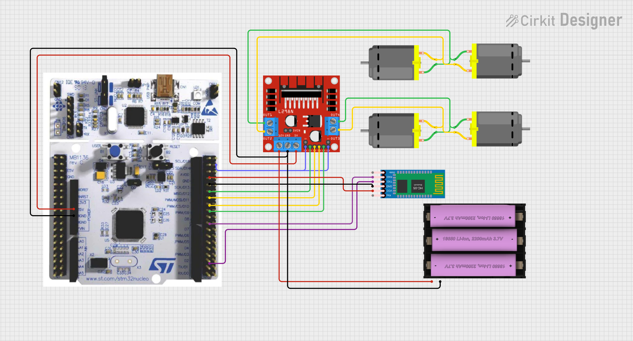
Circuit Documentation
Summary
The circuit in question is designed to control multiple DC motors using an L298N DC motor driver, which is interfaced with an STM32F411RET6 microcontroller. The system also includes a Set battery (7v) for power supply and an HC-05 Bluetooth Module for wireless communication. The microcontroller is responsible for controlling the motor driver, which in turn controls the speed and direction of the DC motors. The Bluetooth module allows for remote control capabilities, receiving commands that the microcontroller can interpret to manage the motors.
Component List
DC Motor
- Description: A standard DC motor used for converting electrical energy into mechanical rotation.
- Pins: pin 1, pin 2
Set battery (7v)
- Description: A 7-volt battery set providing the power source for the circuit.
- Pins: + (positive), - (negative)
HC-05 Bluetooth Module
- Description: A Bluetooth module for wireless communication, allowing the microcontroller to receive commands remotely.
- Pins: Key, VCC, TXD, RXD, State, GND
L298N DC motor driver
- Description: A motor driver module capable of controlling up to two DC motors. It provides the ability to control the speed and direction of the motors.
- Pins: OUT1, OUT2, 12V, GND, 5V, OUT3, OUT4, 5V-ENA-JMP-I, 5V-ENA-JMP-O, +5V-J1, +5V-J2, ENA, IN1, IN2, IN3, IN4, ENB
STM32F411RET6
- Description: A microcontroller unit (MCU) that is the central controller of the circuit, interfacing with the motor driver and Bluetooth module.
- Pins: 5V, GND, PA_5, PA_6, PA_7, PB_6, UART1_RX, PA_9 / UART1_TX, PWM3/1
Wiring Details
DC Motors
- Motor 1 & 2:
- pin 1 connected to L298N DC motor driver OUT4
- pin 2 connected to L298N DC motor driver OUT3
- Motor 3 & 4:
- pin 1 connected to L298N DC motor driver OUT1
- pin 2 connected to L298N DC motor driver OUT2
Set battery (7v)
- Battery:
-
- (positive) connected to L298N DC motor driver 12V
-
- (negative) connected to STM32F411RET6 GND and L298N DC motor driver GND
-
HC-05 Bluetooth Module
- Bluetooth Module:
- VCC connected to STM32F411RET6 5V
- TXD connected to STM32F411RET6 UART1_RX
- RXD connected to STM32F411RET6 PA_9 / UART1_TX
- GND connected to STM32F411RET6 GND
L298N DC motor driver
- Motor Driver:
- 5V connected to STM32F411RET6 5V
- ENA and ENB connected to STM32F411RET6 PWM3/1
- IN1 connected to STM32F411RET6 PA_5
- IN2 connected to STM32F411RET6 PA_6
- IN3 connected to STM32F411RET6 PA_7
- IN4 connected to STM32F411RET6 PB_6
STM32F411RET6
- Microcontroller:
- 5V connected to HC-05 Bluetooth Module VCC and L298N DC motor driver 5V
- GND connected to Set battery (7v) -, HC-05 Bluetooth Module GND, and L298N DC motor driver GND
- PA_5 connected to L298N DC motor driver IN1
- PA_6 connected to L298N DC motor driver IN2
- PA_7 connected to L298N DC motor driver IN3
- PB_6 connected to L298N DC motor driver IN4
- UART1_RX connected to HC-05 Bluetooth Module TXD
- PA_9 / UART1_TX connected to HC-05 Bluetooth Module RXD
- PWM3/1 connected to L298N DC motor driver ENA and ENB
Documented Code
No code was provided for the microcontroller. The documentation of the code would typically include details on how the microcontroller is programmed to interface with the motor driver and the Bluetooth module, including initialization of peripherals, main control loop, interrupt service routines, and any communication protocols used.