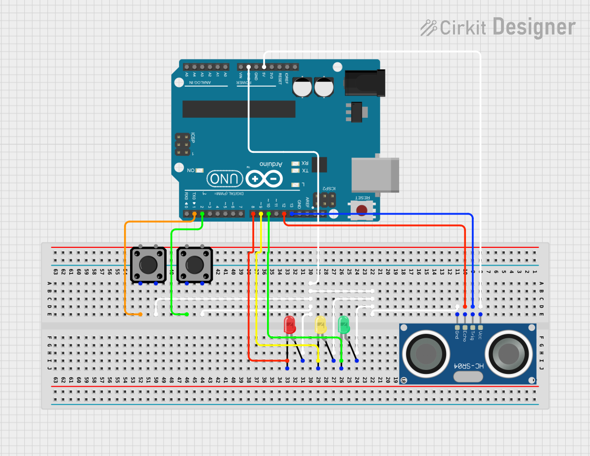
Arduino-Controlled Ultrasonic Sensor with RGB Indicator Lights

Circuit Documentation
Summary
This circuit is designed to interface an HC-SR04 Ultrasonic Sensor with an Arduino UNO microcontroller. The circuit includes three LEDs (red, green, and yellow) and two tactile switch buttons. The HC-SR04 sensor is powered by the Arduino and is connected to two digital pins for triggering and receiving echo signals. Each LED is connected to a separate digital pin on the Arduino for individual control. The tactile switches are also connected to the Arduino to possibly serve as input devices. The ground connections are shared among the components and tied to the Arduino's ground.
Component List
LED: Two Pin (red)
- Description: A red LED with two pins: anode and cathode.
- Purpose: To provide visual indication, typically for signaling or status display.
LED: Two Pin (green)
- Description: A green LED with two pins: anode and cathode.
- Purpose: To provide visual indication, typically for signaling or status display.
LED: Two Pin (yellow)
- Description: A yellow LED with two pins: anode and cathode.
- Purpose: To provide visual indication, typically for signaling or status display.
HC-SR04 Ultrasonic Sensor
- Description: An ultrasonic distance sensor with four pins: VCC, TRIG, ECHO, and GND.
- Purpose: To measure distances by emitting ultrasonic waves and detecting the reflected signal.
Arduino UNO
- Description: A microcontroller board based on the ATmega328P with various digital and analog I/O pins.
- Purpose: To serve as the central controller for the circuit, processing inputs and controlling outputs.
Tactile Switch Buttons - 12mm Square (x2)
- Description: A tactile switch with four pins.
- Purpose: To serve as a user input device, possibly to trigger events or actions in the circuit.
Wiring Details
HC-SR04 Ultrasonic Sensor
- VCC: Connected to Arduino UNO 5V.
- TRIG: Connected to Arduino UNO D13.
- ECHO: Connected to Arduino UNO D12.
- GND: Shared ground with other components and Arduino UNO GND.
LED: Two Pin (red)
- Anode: Shared ground with other components and Arduino UNO GND.
- Cathode: Connected to Arduino UNO D8.
LED: Two Pin (green)
- Anode: Shared ground with other components and Arduino UNO GND.
- Cathode: Connected to Arduino UNO D10.
LED: Two Pin (yellow)
- Anode: Shared ground with other components and Arduino UNO GND.
- Cathode: Connected to Arduino UNO D9.
Tactile Switch Buttons - 12mm Square
- Pin 3: One switch connected to Arduino UNO D2, another to D1.
- Pin 4: Shared ground with other components and Arduino UNO GND.
Documented Code
Arduino UNO Code (sketch.ino)
void setup() {
  // put your setup code here, to run once:

}

void loop() {
  // put your main code here, to run repeatedly:

}
This is the template code for the Arduino UNO. The setup() function is intended to contain initialization code that runs once at the start, such as pin mode declarations. The loop() function is meant for the main code that runs repeatedly, which could include reading sensor data, controlling LEDs, and reading button states. The actual implementation details will depend on the specific requirements of the circuit's operation.