Cirkit Designer
Your all-in-one circuit design IDE
Home /
Project Documentation
Arduino-Based Robotic Arm with RGB Color Detection and Servo Control
Circuit Documentation
Summary
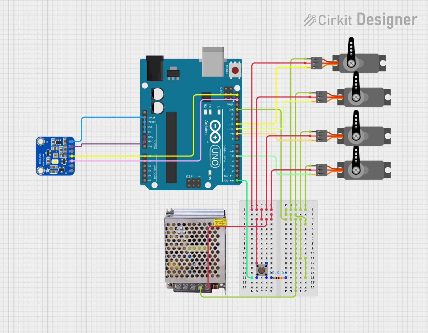
This circuit is designed to control a robotic arm using an Arduino UNO microcontroller. The arm's movements are determined by the color detected by an Adafruit TCS34725 RGB Color Sensor. The circuit includes multiple servos to control different parts of the arm, a pushbutton for user input, and a power supply to provide the necessary voltage and current.
Component List
Adafruit TCS34725 RGB Color Sensor
- Description: RGB color sensor with an IR filter and white LED.
- Pins: LED_EN, INT, SDA, SCL, +3V3, GND, VIN
Servo (4 units)
- Description: Standard servo motor.
- Pins: GND, VCC, PWM
Arduino UNO
- Description: Microcontroller board based on the ATmega328P.
- Pins: UNUSED, IOREF, Reset, 3.3V, 5V, GND, Vin, A0, A1, A2, A3, A4, A5, SCL, SDA, AREF, D13, D12, D11, D10, D9, D8, D7, D6, D5, D4, D3, D2, D1, D0
POWER SUPPLY 5V 5AMP
- Description: Power supply providing 5V and up to 5A.
- Pins: 220V Positive Pole (AC), 220V Negative Pole (AC), GND, GND (DC), 12V-24V Output (DC)
Pushbutton
- Description: Standard pushbutton switch.
- Pins: Pin 3 (out), Pin 4 (out), Pin 1 (in), Pin 2 (in)
Resistor
- Description: 10k Ohm resistor.
- Pins: pin1, pin2
- Properties: Resistance: 10000 Ohms
Wiring Details
Adafruit TCS34725 RGB Color Sensor
- SDA: Connected to Arduino UNO SDA
- SCL: Connected to Arduino UNO SCL
- GND: Connected to Arduino UNO GND
- VIN: Connected to Arduino UNO 5V
Servo 1
- GND: Connected to POWER SUPPLY 5V 5AMP GND (DC)
- VCC: Connected to POWER SUPPLY 5V 5AMP 12V-24V Output (DC)
- PWM: Connected to Arduino UNO D5
Servo 2
- GND: Connected to POWER SUPPLY 5V 5AMP GND (DC)
- VCC: Connected to POWER SUPPLY 5V 5AMP 12V-24V Output (DC)
- PWM: Connected to Arduino UNO D9
Servo 3
- GND: Connected to POWER SUPPLY 5V 5AMP GND (DC)
- VCC: Connected to POWER SUPPLY 5V 5AMP 12V-24V Output (DC)
- PWM: Connected to Arduino UNO D10
Servo 4
- GND: Connected to POWER SUPPLY 5V 5AMP GND (DC)
- VCC: Connected to POWER SUPPLY 5V 5AMP 12V-24V Output (DC)
- PWM: Connected to Arduino UNO D11
Arduino UNO
- GND: Connected to POWER SUPPLY 5V 5AMP GND (DC)
- SDA: Connected to Adafruit TCS34725 RGB Color Sensor SDA
- SCL: Connected to Adafruit TCS34725 RGB Color Sensor SCL
- 5V: Connected to Adafruit TCS34725 RGB Color Sensor VIN
- D0: Connected to Resistor pin1
- D5: Connected to Servo 1 PWM
- D9: Connected to Servo 2 PWM
- D10: Connected to Servo 3 PWM
- D11: Connected to Servo 4 PWM
POWER SUPPLY 5V 5AMP
- GND (DC): Connected to Servo 1 GND, Servo 2 GND, Servo 3 GND, Servo 4 GND, Arduino UNO GND
- 12V-24V Output (DC): Connected to Servo 1 VCC, Servo 2 VCC, Servo 3 VCC, Servo 4 VCC
Pushbutton
- Pin 3 (out): Connected to Pin 1 (in)
- Pin 4 (out): Connected to Pin 2 (in)
- Pin 1 (in): Connected to POWER SUPPLY 5V 5AMP 12V-24V Output (DC)
- Pin 2 (in): Connected to Resistor pin1
Resistor
- pin1: Connected to Pushbutton Pin 2 (in)
- pin2: Connected to POWER SUPPLY 5V 5AMP GND (DC)
Documented Code
#include <Servo.h>
#include <Adafruit_TCS34725.h>
#include <Servo.h>
Adafruit_TCS34725 tcs = Adafruit_TCS34725(TCS34725_INTEGRATIONTIME_50MS, TCS34725_GAIN_4X);

int tiempo1 = 30;
int tiempo2 = 1000;

Servo Cintura;  // Declaramos variable para contolar Servo Cintura
Servo Hombro;   // Declaramos variable para contolar Servo Hombro
Servo Codo;     // Declaramos variable para contolar Servo Codo
Servo Pinzas;   // Declaramos variable para contolar Servo Pinzas

int ang;

void setup() {

  Serial.begin(9600);
  tcs.begin();  // inicializamos el sensor

  Cintura.attach(6);  // Para control servo Cintura asignamos el pin digital 6
  Hombro.attach(9);   // Para control servo Hombro asignamos el pin digital 9
  Codo.attach(10);    // Para control servo Codo asignamos el pin digital 10
  Pinzas.attach(11);  // Para control servo Pinzas asignamos el pin digital 11

  Cintura.write(90);  //  Posición inicial servo cintura  = 90 Grados
  Hombro.write(20);   //  Posición inicial servo hombro = 20 Grados
  Codo.write(50);     //  Posición inicial servo codo = 50 Grados
  Pinzas.write(0);    //  Posición inicial servo pinzas = 0 Grados
}

void loop() {

  float red, green, blue;           // variables para colores R,g,b
  tcs.getRGB(&red, &green, &blue);  // lectura de colores con el sensor
  int R = int(red);
  int G = int(green);
  int B = int(blue);
  String color = "";

  if ((R - B > 10) & (G - B > 25)) {
    color = "BLANCO";
    // ---------------------------------------------------SECUENCIA 1 (COLOR BLANCO) -------------------------------------------------------------------------------

    for (ang = 20; ang < 90; ang++)  //Hombro gira al frente hasta 90 grados
    {
      Hombro.write(ang);
      delay(tiempo1);
    }
    delay(tiempo2);

    Pinzas.write(22);  // Pinzas se cierran hasta 22 grados
    delay(tiempo2);

    for (ang = 90; ang > 20; ang--)  //hombro regresa hasta 30 grados
    {
      Hombro.write(ang);
      delay(tiempo1);
    }
    delay(tiempo2);
    for (ang = 90; ang > 40; ang--)  // Cintura gira a la derecha hasta 40 grados
    {
      Cintura.write(ang);
      delay(tiempo1);
    }
    delay(tiempo2);

    for (ang = 50; ang > 35; ang--)  //codo gira de 50 a 35 grados
    {
      Codo.write(ang);
      delay(tiempo1);
    }

    for (ang = 20; ang < 91; ang++)  //Hombro gira al frente de 20 a 90 grados
    {
      Hombro.write(ang);
      delay(tiempo1);
    }
    delay(500);
    Pinzas.write(0);  // Pinzas se abren hasta la posición de 0 grados

    delay(tiempo2);

    for (ang = 90; ang > 20; ang--)  //hombro regresa de 90 a 20 grados
    {
      Hombro.write(ang);
      delay(tiempo1);
    }
    delay(tiempo2);

    for (ang = 35; ang < 50; ang++)  //Codo regresa  a la posición de  50 grados
    {
      Codo.write(ang);
      delay(tiempo1);
    }

    for (ang = 40; ang < 90; ang++)  // Cintura gira