
Arduino GIGA R1 Wi-Fi Controlled Robotic Arm with Servo and Stepper Motors
View and Edit Project In Cirkit Designer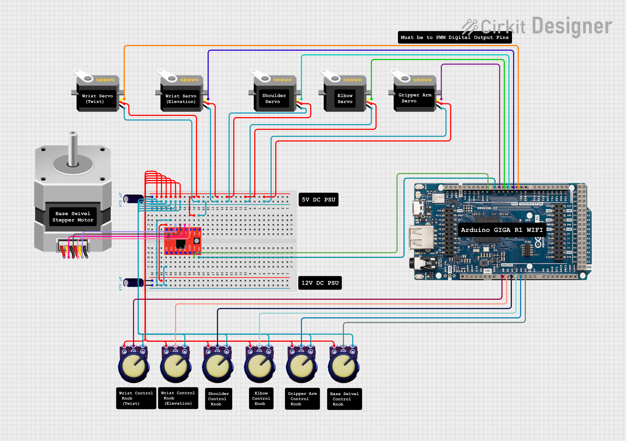
Circuit Documentation
Summary
This circuit involves an Arduino GIGA R1 WIFI microcontroller, several servos, a stepper motor with its driver, and multiple potentiometers. The circuit is designed to control the servos and the stepper motor, with the potentiometers providing variable input. The Arduino GIGA R1 WIFI serves as the central control unit, interfacing with all other components.
Component List
Arduino GIGA R1 WIFI
- Description: A versatile microcontroller board with built-in WiFi capabilities.
- Pins: SLC1, SDA1, AREF, GND, SCK13, CIPO12, COPI11, CS10, SDA2 9, SCL2 8, 7, 6, 5, 4, 3, 2, TX0 1, RX0 0, TX3 14, RX3 15, TX2 16, RX2 17, TX1 18, RX1 19, SDA 20, SCL 21, 5V, 22, 23, 24, 25, 26, 27, 28, 29, 30, 31, 32, 33, 34, 35, 36, 37, 38, 39, 40, 41, 42, 43, 44, 45, 46, 47, 48, 49, 50, 51, 52, 53, A8, A9, A10, A11, DAC0, DAC1, CANRX, CANTX, IOREF, RESET, 3.3V, VIN, A0, A1, A2, A3, A4, A5, A6, A7
Servo
- Description: A small motor with a feedback mechanism for precise control.
- Pins: gnd, vcc, pulse
Stepper Motor (Unipolar)
- Description: A motor that moves in discrete steps, allowing for precise control of angular position.
- Pins: D, COMMON_2, B, C, COMMON_1, A
A4988 Stepper Motor Driver (Red)
- Description: A driver module for controlling stepper motors.
- Pins: ENABLE, MS1, MS2, MS3, RESET, SLEEP, STEP, DIR, VMOT, GND, 2B, 2A, 1A, 1B, VDD
Potentiometer
- Description: A variable resistor used to adjust levels of voltage.
- Pins: GND, Output, VCC
Electrolytic Capacitor
- Description: A capacitor with a larger capacitance value, used for filtering and energy storage.
- Pins: -, +
- Properties:
- Capacitance: 0.00047 Farads
Wiring Details
Arduino GIGA R1 WIFI
- Pin 7 connected to DIR pin of A4988 Stepper Motor Driver (Red)
- Pin SCL2 8 connected to STEP pin of A4988 Stepper Motor Driver (Red)
- Pin 6 connected to pulse pin of Servo
- Pin 5 connected to pulse pin of Servo
- Pin 4 connected to pulse pin of Servo
- Pin 3 connected to pulse pin of Servo
- Pin 2 connected to pulse pin of Servo
- Pin A0 connected to Output pin of Potentiometer
- Pin A1 connected to Output pin of Potentiometer
- Pin A2 connected to Output pin of Potentiometer
- Pin A3 connected to Output pin of Potentiometer
- Pin A4 connected to Output pin of Potentiometer
- Pin A5 connected to Output pin of Potentiometer
Servo
- gnd connected to GND pin of A4988 Stepper Motor Driver (Red)
- vcc connected to VDD pin of A4988 Stepper Motor Driver (Red)
- pulse connected to respective pins on Arduino GIGA R1 WIFI (6, 5, 4, 3, 2)
Stepper Motor (Unipolar)
- Pin B connected to 1B pin of A4988 Stepper Motor Driver (Red)
- Pin COMMON_1 connected to 1A pin of A4988 Stepper Motor Driver (Red)
- Pin C connected to 2A pin of A4988 Stepper Motor Driver (Red)
- Pin COMMON_2 connected to 2B pin of A4988 Stepper Motor Driver (Red)
A4988 Stepper Motor Driver (Red)
- GND connected to - pin of Electrolytic Capacitor
- DIR connected to Pin 7 of Arduino GIGA R1 WIFI
- VDD connected to + pin of Electrolytic Capacitor
- STEP connected to Pin SCL2 8 of Arduino GIGA R1 WIFI
- 1B connected to Pin B of Stepper Motor (Unipolar)
- 1A connected to Pin COMMON_1 of Stepper Motor (Unipolar)
- 2A connected to Pin C of Stepper Motor (Unipolar)
- 2B connected to Pin COMMON_2 of Stepper Motor (Unipolar)
- ENABLE connected to GND pin of A4988 Stepper Motor Driver (Red)
- VMOT connected to + pin of Electrolytic Capacitor
Potentiometer
- GND connected to GND pin of A4988 Stepper Motor Driver (Red)
- Output connected to respective pins on Arduino GIGA R1 WIFI (A0, A1, A2, A3, A4, A5)
- VCC connected to VDD pin of A4988 Stepper Motor Driver (Red)
Electrolytic Capacitor
- - connected to GND pin of A4988 Stepper Motor Driver (Red)
- + connected to VDD pin of A4988 Stepper Motor Driver (Red)
Code
No code provided for this circuit.
This documentation provides a comprehensive overview of the circuit, including a detailed list of components and their wiring connections.