Cirkit Designer
Your all-in-one circuit design IDE
Home /
Project Documentation
Arduino UNO Controlled LED Circuit
Circuit Documentation
Summary of the Circuit
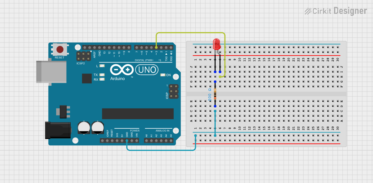
This circuit consists of an Arduino UNO microcontroller, a red two-pin LED, and a resistor. The Arduino UNO is used as the control unit to manage the LED's state, turning it on or off. The LED serves as an indicator or a visual output device. The resistor is used to limit the current flowing through the LED to prevent it from burning out.
Component List
Arduino UNO
- Description: A microcontroller board based on the ATmega328P.
- Pins: UNUSED, IOREF, Reset, 3.3V, 5V, GND, Vin, A0-A5, SCL, SDA, AREF, D0-D13.
- Purpose: Acts as the central processing unit of the circuit, controlling the LED.
LED: Two Pin (red)
- Description: A basic red light-emitting diode.
- Pins: Anode, Cathode.
- Purpose: Serves as a visual indicator when powered.
Resistor
- Description: A passive two-terminal electrical component that implements electrical resistance as a circuit element.
- Pins: Pin1, Pin2.
- Properties: Resistance - 200 Ohms.
- Purpose: Limits the current through the LED to prevent damage.
Wiring Details
Arduino UNO
- GND is connected to the Resistor (Pin1).
- D3 is connected to the LED (Anode).
LED: Two Pin (red)
- Anode is connected to Arduino UNO (D3).
- Cathode is connected to Resistor (Pin2).
Resistor
- Pin1 is connected to Arduino UNO (GND).
- Pin2 is connected to LED (Cathode).
Documented Code
Arduino UNO Code (sketch.ino)
void setup() {
  // put your setup code here, to run once:

}

void loop() {
  // put your main code here, to run repeatedly:

}
Additional Files
- documentation.txt: This file is empty and does not contain any code or comments.
The provided code is a template and does not contain any functionality to control the LED. To complete this circuit's functionality, code should be added to the setup() function to initialize pin D3 as an output and to the loop() function to turn the LED on and off.