Cirkit Designer
Your all-in-one circuit design IDE
Home /
Project Documentation
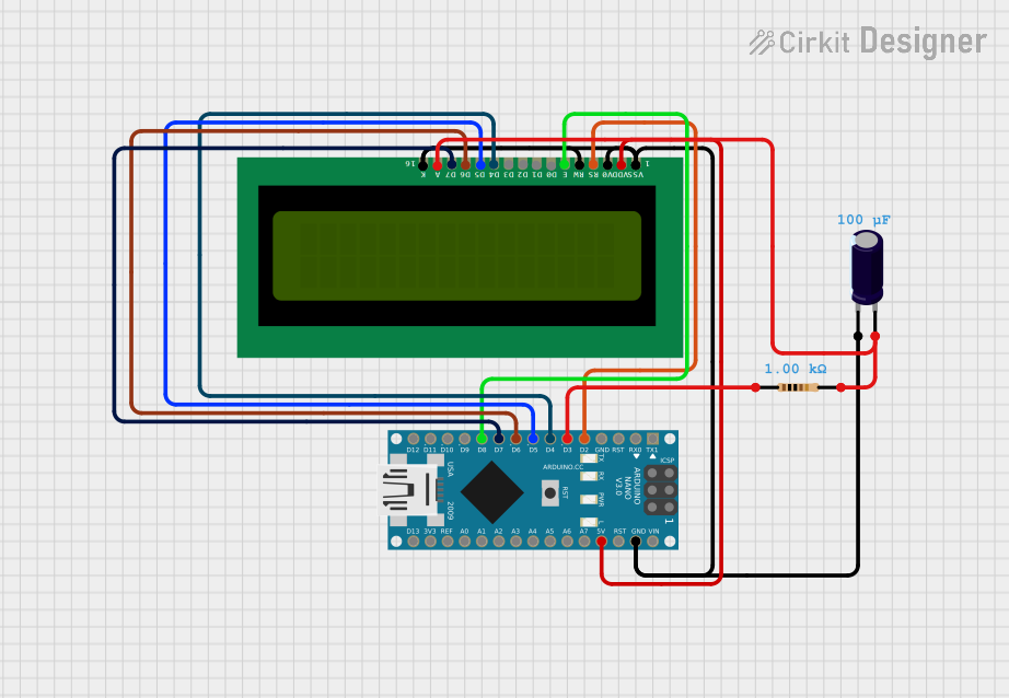
Arduino Nano Controlled LCD Interface

Circuit Documentation
Summary of the Circuit
This circuit consists of an Arduino Nano microcontroller interfaced with a 16x2 LCD display, an electrolytic capacitor, and a resistor. The Arduino Nano is responsible for controlling the LCD display, which is used to show information to the user. The electrolytic capacitor and resistor are likely used for power supply filtering and voltage/current control for the LCD backlight, respectively.
Component List
Arduino Nano
- Description: A compact microcontroller board based on the ATmega328P.
- Pins: D1/TX, D0/RX, RESET, GND, D2, D3, D4, D5, D6, D7, D8, D9, D10, D11/MOSI, D12/MISO, VIN, 5V, A7, A6, A5, A4, A3, A2, A1, A0, AREF, 3V3, D13/SCK.
16X2 LCD
- Description: A liquid crystal display capable of displaying 16 characters per line across 2 lines.
- Pins: VSS, VDD, V0, RS, RW, E, D1, D0, D2, D3, D4, D6, D5, D7, A, K.
Electrolytic Capacitor
- Description: A polarized capacitor with a capacitance value of 0.0001 Farads.
- Pins: -, +.
Resistor
- Description: A passive two-terminal electrical component with a resistance of 1000 Ohms.
- Pins: pin1, pin2.
Wiring Details
Arduino Nano
- D2 connected to 16X2 LCD RS
- D3 connected to Resistor pin1
- D4 connected to 16X2 LCD D4
- D5 connected to 16X2 LCD D5
- D6 connected to 16X2 LCD D6
- D7 connected to 16X2 LCD D7
- D8 connected to 16X2 LCD E
- GND connected to Electrolytic Capacitor -, 16X2 LCD VSS, 16X2 LCD K, 16X2 LCD V0, 16X2 LCD RW
- 5V connected to 16X2 LCD VDD
16X2 LCD
- RS connected to Arduino Nano D2
- D4 connected to Arduino Nano D4
- D5 connected to Arduino Nano D5
- D6 connected to Arduino Nano D6
- D7 connected to Arduino Nano D7
- E connected to Arduino Nano D8
- VSS, K, V0, RW connected to Arduino Nano GND
- VDD connected to Arduino Nano 5V
- A connected to Resistor pin2
Electrolytic Capacitor
- (negative) connected to Arduino Nano GND
- (positive) connected to Resistor pin2
Resistor
- pin1 connected to Arduino Nano D3
- pin2 connected to Electrolytic Capacitor +, 16X2 LCD A
Documented Code
Arduino Nano Code (sketch.ino)
void setup() {
  // put your setup code here, to run once:

}

void loop() {
  // put your main code here, to run repeatedly:

}
16X2 LCD Code (sketch.ino)
void setup() {
  // put your setup code here, to run once:

}

void loop() {
  // put your main code here, to run repeatedly:

}
Note: The code provided for both the Arduino Nano and the 16X2 LCD is a template with empty setup and loop functions. The actual functionality needs to be implemented according to the requirements of the application.