
Raspberry Pi Pico-based PS2 Controller Emulator with ADS1115 Analog Input
View and Edit Project In Cirkit Designer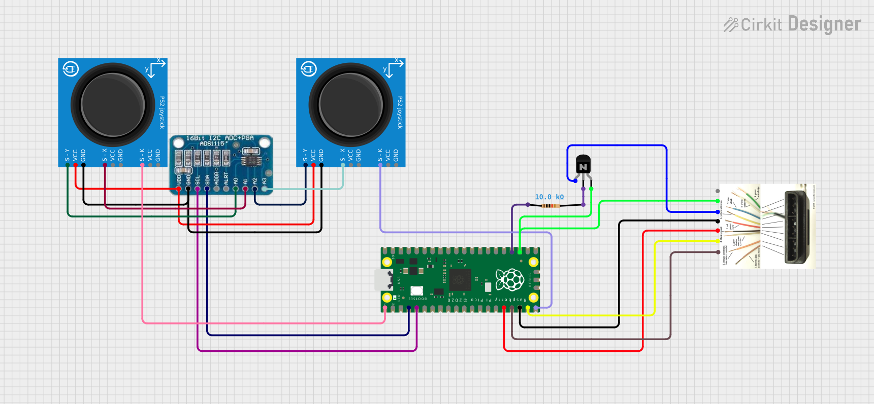
Circuit Documentation
Summary
This circuit integrates a Raspberry Pi Pico microcontroller with an ADS1115 analog-to-digital converter (ADC), two PS2 Joysticks, a PS2 cable from a console, an NPN transistor, and a resistor. The Raspberry Pi Pico is programmed to emulate a PS2 controller, interfacing with the PS2 cable and joysticks to capture user inputs. The ADS1115 ADC is used to read analog signals from the joysticks, which are then processed by the Raspberry Pi Pico to determine the joystick positions. The NPN transistor is likely used as a switch or amplifier for signals from the PS2 cable. The resistor is used to set the base current of the NPN transistor.
Component List
Raspberry Pi Pico
- Microcontroller board based on the RP2040 microcontroller chip.
- Features multiple GPIO pins for interfacing with other components.
ADS1115
- 16-bit precision analog-to-digital converter (ADC).
- I2C interface for communication with microcontroller.
- Four single-ended or two differential inputs.
PS2 Joystick (x2)
- Analog joystick module with X and Y axis control.
- Includes a pushbutton switch (S - K).
NPN Transistor (CBE)
- Bipolar junction transistor used for switching or amplification.
- Three terminals: collector, base, and emitter.
Resistor
- Passive component used to limit current or divide voltages.
- Resistance value: 10,000 Ohms.
Ps2 cable from console
- Cable used to connect the circuit to a PS2 console.
- Includes various signal lines for communication and power.
Wiring Details
Raspberry Pi Pico
pin 1connected to PS2 Joystick S - K (button switch).pin 4(SDA) connected to ADS1115 SDA.pin 5(SCL) connected to ADS1115 SCL.pin 16connected to PS2 cable PIN_DATA-(MISO).pin 17connected to PS2 cable PIN_ATT-(SS).pin 18connected to PS2 cable PIN_CLK-(SCK).pin 19connected to PS2 cable PIN_CMD-(MOSI).pin 20connected to second PS2 Joystick S - K (button switch).pin 23connected to NPN Transistor emitter and PS2 cable PIN-GND.pin 24connected to Resistor pin1.
ADS1115
VDDconnected to PS2 Joystick VCC, second PS2 Joystick VCC.GNDconnected to PS2 Joystick GND, second PS2 Joystick GND.SCLconnected to Raspberry Pi Pico pin 5.SDAconnected to Raspberry Pi Pico pin 4.A0connected to PS2 Joystick S - Y.A1connected to PS2 Joystick S - X.A2connected to second PS2 Joystick S - Y.A3connected to second PS2 Joystick S - X.
PS2 Joystick
S - Yconnected to ADS1115 A0.VCCconnected to ADS1115 VDD.GNDconnected to ADS1115 GND.S - Xconnected to ADS1115 A1.S - Kconnected to Raspberry Pi Pico pin 1.
Second PS2 Joystick
S - Yconnected to ADS1115 A2.VCCconnected to ADS1115 VDD.GNDconnected to ADS1115 GND.S - Xconnected to ADS1115 A3.S - Kconnected to Raspberry Pi Pico pin 20.
NPN Transistor (CBE)
emitterconnected to Raspberry Pi Pico pin 23 and PS2 cable PIN-GND.collectorconnected to PS2 cable PIN_ACK-Ack pin.baseconnected to Resistor pin2.
Resistor
pin1connected to Raspberry Pi Pico pin 24.pin2connected to NPN Transistor base.
Ps2 cable from console
PIN_ATT-(SS)connected to Raspberry Pi Pico pin 17.PIN_CMD-(MOSI)connected to Raspberry Pi Pico pin 19.PIN_DATA-(MISO)connected to Raspberry Pi Pico pin 16.PIN_CLK-(SCK)connected to Raspberry Pi Pico pin 18.PIN_ACK-Ack pinconnected to NPN Transistor collector.PIN-GNDconnected to NPN Transistor emitter and Raspberry Pi Pico pin 23.PIN-3.3vnot mentioned in the net list, assumed to be connected to a power source.
Documented Code
The code for the Raspberry Pi Pico is written in C++ and is designed to emulate a PS2 controller. It includes the necessary libraries for SPI and I2C communication, as well as EEPROM for storing calibration data. The code defines various constants for PS2 controller commands, button bitmasks, and pin definitions. It sets up the SPI and I2C interfaces, initializes global variables, and contains functions for handling SPI transfers, processing received data, reading from the ADS1115 ADC, and updating the controller state based on button presses and joystick movements.
The code also includes calibration routines for the analog sticks, functions to toggle analog mode, and debug output to the serial port for monitoring the controller state. The main loop continuously updates the controller state and checks for button presses to toggle analog mode or enter calibration mode.
The code is well-structured and includes comments explaining the purpose of each function and variable. It is designed to be uploaded to the Raspberry Pi Pico microcontroller using the Arduino IDE or a similar development environment.
// Code omitted for brevity. Please refer to the provided code input for the full source code.
Please note that the actual code was not included in this document due to its length. The provided code input should be referred to for the complete source code and further details.