
ESP32-Based Smart Power Socket Controller with Current Sensing
View and Edit Project In Cirkit Designer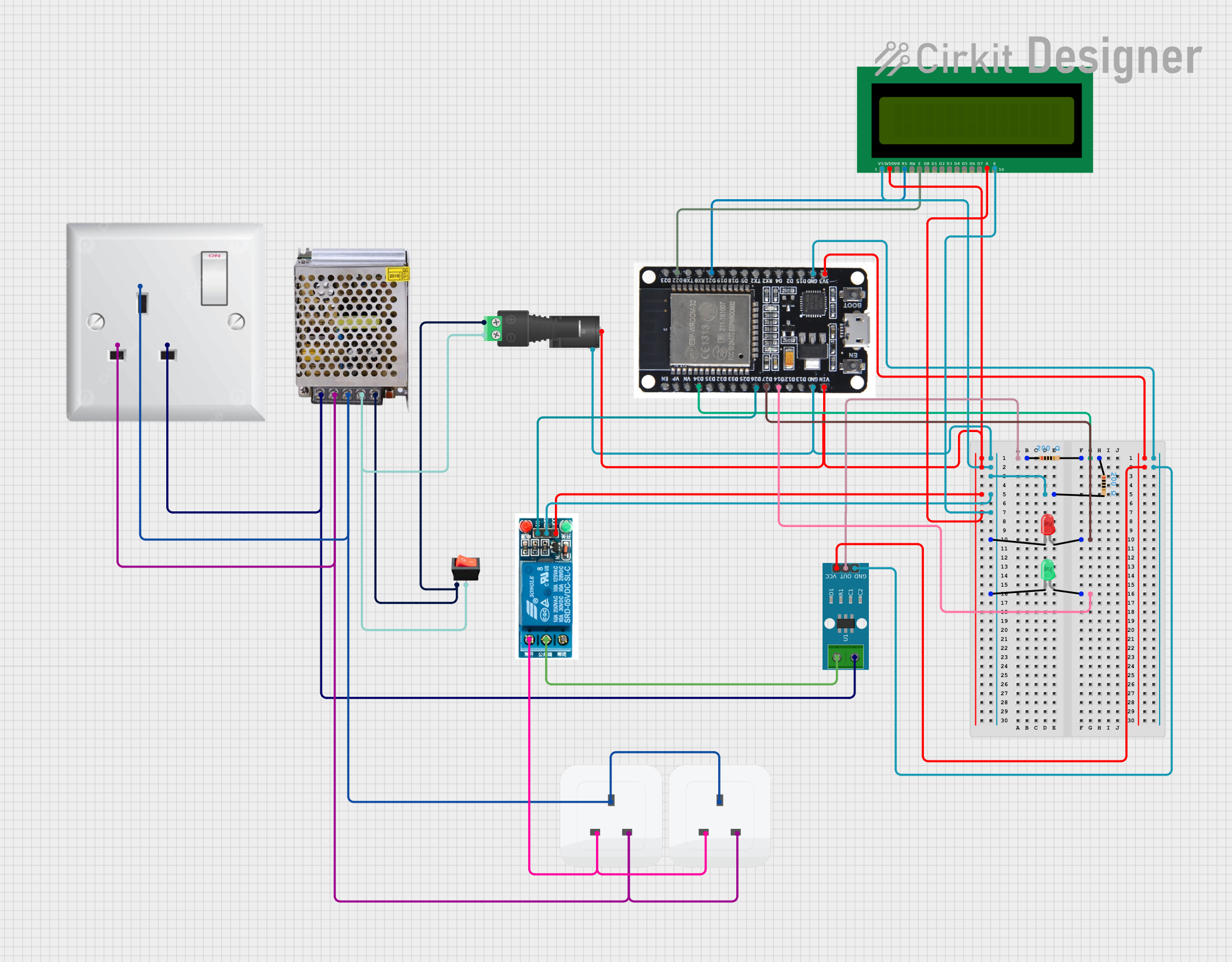
Circuit Documentation
Summary
This document provides a detailed overview of a circuit designed to interface various components with an ESP32 microcontroller. The circuit includes power supply elements, a current sensor, a relay, LEDs, resistors, and an LCD display. The ESP32 serves as the central processing unit, controlling the relay and LEDs, and receiving data from the current sensor. The circuit is powered by a 12V power supply, which is regulated down to the voltage levels appropriate for the ESP32 and other components.
Component List
AC Wall Plug Point
- Description: Provides AC power from a standard wall outlet.
- Pins: Earth (E), Neutral (N), Line (L)
ESP32
- Description: A microcontroller with Wi-Fi and Bluetooth capabilities.
- Pins: EN, VP, VN, D34, D35, D32, D33, D25, D26, D27, D14, D12, D13, GND, VIN, 3V3, D15, D2, D4, RX2, TX2, D5, D18, D19, D21, RX0, TX0, D22, D23, BOOT
2.1mm DC Barrel Jack
- Description: A connector for DC power input.
- Pins: Switch, Sleeve, Center
Rocker Switch
- Description: A switch to control the power flow.
- Pins: Output, Input
Resistor (200 Ohms)
- Description: Limits current or divides voltage.
- Properties: Resistance: 200 Ohms
16X2 LCD
- Description: A liquid crystal display for showing information.
- Pins: VSS, VDD, V0, RS, RW, E, D0-D7, A, K
2.1mm Barrel Jack with Terminal Block
- Description: A connector for attaching wires to a barrel jack.
- Pins: Positive (POS), Negative (NEG)
ACS712 Current Sensor
- Description: Measures current passing through it.
- Pins: 1, 2, GND, OUT, VCC
5V Relay
- Description: An electromechanical switch controlled by an electrical signal.
- Pins: Normally Open (NO), Common terminal (COM), Normally Closed (NC), Input (In), GND, VCC
Socket
- Description: A connector for plugging in devices.
- Pins: Earth, Life, Neutral
LED: Two Pin (Green)
- Description: A green light-emitting diode.
- Pins: Cathode, Anode
LED: Two Pin (Red)
- Description: A red light-emitting diode.
- Pins: Cathode, Anode
POWER SUPPLY 12V 5AMP
- Description: Provides a 12V DC output from a 220V AC input.
- Pins: 220V Positive Pole (AC), 220V Negative Pole (AC), GND, GND (DC), 12V-24V Output (DC)
Wiring Details
AC Wall Plug Point
- Earth (E) connected to the earth pins of sockets and GND of the power supply.
- Neutral (N) connected to the neutral pins of sockets and 220V Negative Pole (AC) of the power supply.
- Line (L) connected to the Line pin of the ACS712 Current Sensor.
ESP32
- D34 connected to a 200 Ohm resistor.
- GND connected to the sleeve of the DC Barrel Jack, VSS and K of the LCD, GND of the relay, and GND of the ACS712 Current Sensor.
- VIN connected to the center of the DC Barrel Jack, VDD and A of the LCD, and VCC of the relay.
- 3V3 connected to VCC of the ACS712 Current Sensor.
- D27 connected to the anode of the red LED.
- D14 connected to the anode of the green LED.
- D21 connected to RS of the LCD.
- D22 connected to E of the LCD.
- D26 connected to the input of the relay.
2.1mm DC Barrel Jack
- Sleeve connected to GND of the ESP32 and other components.
- Center connected to VIN of the ESP32 and other components.
Rocker Switch
- Output connected to the NEG of the Barrel Jack with Terminal Block.
- Input connected to the POS of the Barrel Jack with Terminal Block.
Resistor (200 Ohms)
- One end connected to the OUT of the ACS712 Current Sensor.
- The other end connected to another 200 Ohm resistor and D34 of the ESP32.
16X2 LCD
- VSS connected to GND of the ESP32.
- VDD connected to VIN of the ESP32.
- RS connected to D21 of the ESP32.
- E connected to D22 of the ESP32.
- A connected to VIN of the ESP32.
- K connected to GND of the ESP32.
ACS712 Current Sensor
- OUT connected to a 200 Ohm resistor.
- VCC connected to 3V3 of the ESP32.
- GND connected to GND of the ESP32.
- 1 connected to the Common terminal of the relay.
- 2 connected to the 220V Positive Pole (AC) of the power supply.
5V Relay
- GND connected to GND of the ESP32.
- VCC connected to VIN of the ESP32.
- In connected to D26 of the ESP32.
- Common terminal connected to 1 of the ACS712 Current Sensor.
- Normally Open connected to the life pins of the sockets.
LED: Two Pin (Green)
- Cathode connected to GND of the ESP32.
- Anode connected to D14 of the ESP32.
LED: Two Pin (Red)
- Cathode connected to GND of the ESP32.
- Anode connected to D27 of the ESP32.
POWER SUPPLY 12V 5AMP
- GND connected to the earth pins of sockets and the NEG of the Barrel Jack with Terminal Block.
- 220V Negative Pole (AC) connected to the neutral pins of sockets.
- 220V Positive Pole (AC) connected to 2 of the ACS712 Current Sensor.
- GND (DC) connected to the NEG of the Barrel Jack with Terminal Block.
- 12V-24V Output (DC) connected to the POS of the Barrel Jack with Terminal Block.
Documented Code
ESP32 Microcontroller Code (Instance ID: 79c68616-4cab-4018-9729-178f6e3c537b)
void setup() {
  // Initialize the digital pins as outputs:
  pinMode(D34, OUTPUT);
  pinMode(D27, OUTPUT);
  pinMode(D14, OUTPUT);
  pinMode(D21, OUTPUT);
  pinMode(D22, OUTPUT);
  pinMode(D26, OUTPUT);
}

void loop() {
  // Example code to blink the LEDs and control the relay:
  digitalWrite(D27, HIGH);   // Turn on the red LED
  digitalWrite(D14, LOW);    // Turn off the green LED
  delay(1000);               // Wait for a second
  digitalWrite(D27, LOW);    // Turn off the red LED
  digitalWrite(D14, HIGH);   // Turn on the green LED
  delay(1000);               // Wait for a second

  // Control the relay:
  digitalWrite(D26, HIGH);   // Activate the relay
  delay(2000);               // Wait for 2 seconds
  digitalWrite(D26, LOW);    // Deactivate the relay
}
(Note: The provided code is a basic example. The actual application code will depend on the specific requirements of the circuit's use case.)
Additional Notes
- The code for the microcontroller with instance ID
e31e1091-0e03-4bda-a7e5-c5fb826ad69fis not provided or is empty. - The code for the microcontroller with instance ID
9e51578d-f743-4ad7-b04b-1fac35904470is a template without specific functionality.
Please ensure that the actual application code is written and uploaded to the microcontrollers for the circuit to perform its intended functions.