Cirkit Designer
Your all-in-one circuit design IDE
Home /
Project Documentation
Arduino UNO Alcohol Detection System with GPS and GSM Module
Circuit Documentation
Summary
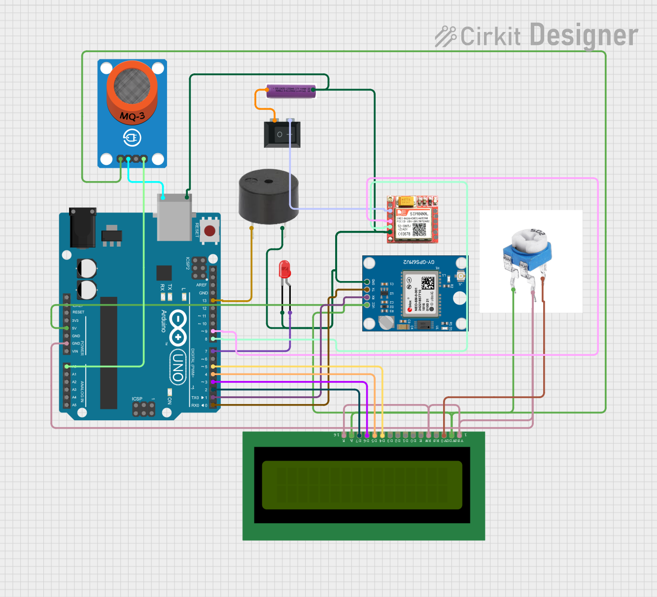
This document provides a detailed overview of a circuit designed to detect alcohol levels and send GPS coordinates via SMS when a threshold is exceeded. The circuit includes an Arduino UNO, an alcohol sensor (MQ-3), a SIM800L GSM module, a Neo 6M GPS module, an LCD display, a buzzer, an LED, a rocker switch, and a 3.7V battery. The Arduino UNO reads the alcohol sensor data, displays it on the LCD, and if the alcohol level exceeds a predefined threshold, it sends an SMS with the GPS coordinates and activates a buzzer and LED.
Component List
Buzzer
- Pins: PIN, GND
- Description: Emits sound when activated.
- Purpose: Alerts when the alcohol level exceeds the threshold.
LED: Two Pin (red)
- Pins: Cathode, Anode
- Description: Red LED.
- Purpose: Indicates high alcohol level.
MQ-3 Breakout
- Pins: VCC, GND, DO, AO
- Description: Alcohol sensor.
- Purpose: Detects alcohol levels.
3.7V Battery
- Pins: +, -
- Description: Power source.
- Purpose: Supplies power to the circuit.
Rocker Switch (SPST)
- Pins: 1, 2
- Description: Single-pole single-throw switch.
- Purpose: Controls power to the SIM800L module.
SIM800L
- Pins: NFT, RING, VCC, DTR, RST, MIC +, RXD, MIC-, TXD, SPK+, GND, SPK-
- Description: GSM module.
- Purpose: Sends SMS with GPS coordinates.
Neo 6M GPS Module
- Pins: GND, TX, RX, VCC
- Description: GPS module.
- Purpose: Provides GPS coordinates.
LCD 16x2 (Wokwi Compatible)
- Pins: VSS, VDD, V0, RS, RW, E, D0, D1, D2, D3, D4, D5, D6, D7, A, K
- Description: 16x2 character LCD.
- Purpose: Displays alcohol level and status messages.
5k Preset
- Pins: Fixed end 1, Fixed end 2, Variable end
- Description: Adjustable resistor.
- Purpose: Adjusts the contrast of the LCD.
Arduino UNO
- Pins: UNUSED, IOREF, Reset, 3.3V, 5V, GND, Vin, A0, A1, A2, A3, A4, A5, SCL, SDA, AREF, D13, D12, D11, D10, D9, D8, D7, D6, D5, D4, D3, D2, D1, D0, +, -
- Description: Microcontroller board.
- Purpose: Controls the entire circuit.
Wiring Details
Buzzer
- PIN connected to Arduino UNO D13
- GND connected to Common Ground
LED: Two Pin (red)
- Anode connected to Arduino UNO D7
- Cathode connected to Common Ground
MQ-3 Breakout
- VCC connected to Arduino UNO 5V
- GND connected to Arduino UNO GND
- AO connected to Arduino UNO A0
3.7V Battery
- + connected to Rocker Switch (SPST) Pin 1
- - connected to Common Ground
Rocker Switch (SPST)
- Pin 1 connected to 3.7V Battery +
- Pin 2 connected to SIM800L VCC
SIM800L
- GND connected to Common Ground
- VCC connected to Rocker Switch (SPST) Pin 2
- RXD connected to Arduino UNO D9
- TXD connected to Arduino UNO D8
Neo 6M GPS Module
- GND connected to Common Ground
- VCC connected to Arduino UNO 5V
- TX connected to Arduino UNO D0
- RX connected to Arduino UNO D1
LCD 16x2 (Wokwi Compatible)
- VSS connected to Common Ground
- VDD connected to Arduino UNO 5V
- V0 connected to 5k Preset Variable End
- RS connected to Arduino UNO D12
- RW connected to Common Ground
- E connected to Arduino UNO D11
- D4 connected to Arduino UNO D5
- D5 connected to Arduino UNO D4
- D6 connected to Arduino UNO D3
- D7 connected to Arduino UNO D2
- A connected to Arduino UNO 5V
- K connected to Common Ground
5k Preset
- Fixed End 1 connected to Arduino UNO 5V
- Fixed End 2 connected to Common Ground
- Variable End connected to LCD 16x2 V0
Documented Code
#include <SoftwareSerial.h>
SoftwareSerial sim(8, 9);
#include <TinyGPS++.h>
#include <LiquidCrystal.h>
const int rs = 12, en = 11, d4 = 5, d5 = 4, d6 = 3, d7 = 2;
LiquidCrystal lcd(rs, en, d4, d5, d6, d7);
float lattitude, longitude;
SoftwareSerial gpsSerial(0, 1); // rx, tx
TinyGPSPlus gps; // create gps object

int value; // variable to hold the value of alcohol

#define motor 10
#define buzzer 13
#define led 7

String number = "+919889342918"; // -> change with your number
int a;

void setup()
{
  pinMode(motor, OUTPUT);
  pinMode(buzzer, OUTPUT);
  pinMode(led, OUTPUT);
  a = 700;
  Serial.begin(9600);
  lcd.begin(16, 2);
  lcd.setCursor(0, 0);
  lcd.print("    Subscribe");
  lcd.setCursor(0, 1);
  lcd.print(" AEROTECH INDIA");
  sim.begin(9600);
  gpsSerial.begin(9600); // connect gps sensor
  delay(6000);
  lcd.clear();
}

void loop()
{
  value = analogRead(A0); // reading value from Arduino analog pin which is receiving value from sensor pin
  lcd.setCursor(0, 0); // setting cursor on LCD's 0th row and 0th column
  lcd.print("value of alcohol"); // writing string on LCD
  lcd.setCursor(0, 1); // setting cursor on 0th column of 1st row
  lcd.print(value); // printing value on LCD
  delay(100); // waiting for 100 milliseconds
  digitalWrite(motor, HIGH);
  digitalWrite(buzzer, LOW);
  digitalWrite(led, LOW);

  if (value > a)
  {
    SendMessage();
  }
}

void SendMessage()
{
  digitalWrite(motor, LOW);
  digitalWrite(buzzer, HIGH);

  boolean newData = false;

  for (unsigned long start = millis(); millis() - start < 2000;)
  {
    while (gpsSerial.available() > 0)
    {
      if (gps.encode(gpsSerial.read()))
      {
        newData = true;
      }
    }
  }

  if (newData)
  {
    Serial.print("Latitude= ");
    Serial.print(gps.location.lat(), 6);
    Serial.print(" Longitude= ");
    Serial.println(gps.location.lng(), 6);
    newData = false;
    delay(300);

    sim.println("AT+CMGF=1");
    delay(200);
    sim.println("AT+CMGS=\"" + number + "\"\r");
    delay(200);
    sim.print("http://maps.google.com/maps?q=loc:");
    sim.print(gps.location.lat(), 6);
    sim.print(",");
    sim.print(gps.location.lng(), 6);
    delay(100);
    sim.println((char)26); // ASCII code for ctrl-26
    delay(200);
    Serial.println("GPS Location SMS Sent Successfully.");

    lcd.clear();
    lcd.setCursor(0, 0);
    lcd.print("Sending ... ");
    lcd.setCursor(0, 1);
    lcd.print("Your Location");
    delay(5000);
    lcd.clear();
    delay(200);
    digitalWrite(buzzer, LOW);

    while (1)
    {
      digitalWrite(led, HIGH