Cirkit Designer
Your all-in-one circuit design IDE
Home /
Project Documentation
GSM-Based Automated Irrigation System with Moisture Sensing and Water Level Monitoring
Circuit Documentation
Summary
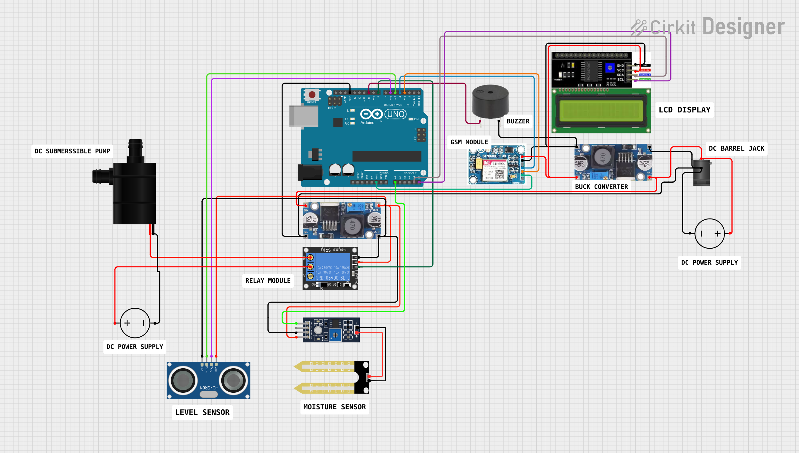
The circuit is designed to monitor and control an irrigation system using an Arduino UNO as the central processing unit. It features a GSM module for remote communication, a humidity sensor for soil moisture measurement, an ultrasonic sensor for water tank level detection, a relay to control a water pump, an LCD display for real-time status updates, and a buzzer for audio alerts. The system is powered by two DC power sources, with step-down buck converters to regulate the voltage. The Arduino UNO is programmed to read sensor data, control the pump via the relay, display information on the LCD, and communicate with a user via SMS using the GSM module.
Component List
- 2.1mm DC Barrel Jack: A power connector for DC supply.
- 1-Channel Relay (5V 10A): An electromechanical switch used to control the water pump.
- Humidity YL-69: A sensor for measuring soil moisture levels.
- Arduino UNO: A microcontroller board based on the ATmega328P.
- LCD I2C Display: A liquid crystal display with an I2C interface for showing information.
- SIM 800L V2.0 GSM: A GSM module for cellular communication.
- Buzzer: An audio signaling device.
- Step down Buck Converter: A voltage regulator to step down the input voltage to a lower output voltage.
- HC-SR04 Ultrasonic Sensor: A sensor for measuring distance via ultrasonic waves, used here to determine the water level in the tank.
- Water Pump: An electric pump for moving water.
- DC Power Source: Provides electrical power to the circuit.
Wiring Details
2.1mm DC Barrel Jack
- Switch: Connected to the step-down buck converter's IN - GND.
- Sleeve: Not connected.
- Center: Connected to the positive terminal of the DC power source.
1-Channel Relay (5V 10A)
- NC (Normally Closed): Not connected.
- Signal: Controlled by Arduino UNO's D8 pin.
- C (Common): Connected to the positive terminal of a DC power source.
- Power: Connected to the OUT + of a step-down buck converter.
- NO (Normally Open): Connected to the water pump's VCC.
- Ground: Connected to the OUT - GND of a step-down buck converter.
Humidity YL-69
- A0: Connected to Arduino UNO's A0 pin.
- D0: Not connected.
- GND: Connected to the OUT - GND of a step-down buck converter.
- VCC: Connected to the OUT + of a step-down buck converter.
Arduino UNO
- GND: Connected to various GND pins of other components and the negative terminal of a DC power source.
- A0: Connected to the Humidity YL-69 A0 pin.
- A4 (SDA): Connected to the LCD I2C Display SDA pin.
- A5 (SCL): Connected to the LCD I2C Display SCL pin.
- D10: Connected to the buzzer's PIN.
- D8: Connected to the 1-Channel Relay signal pin.
- D6: Connected to the HC-SR04 Ultrasonic Sensor TRIG pin.
- D5: Connected to the HC-SR04 Ultrasonic Sensor ECHO pin.
- D4: Connected to the SIM 800L V2.0 GSM SIM_TXD pin.
- D3: Connected to the SIM 800L V2.0 GSM SIM.RXD pin.
LCD I2C Display
- GND: Connected to the OUT - GND of a step-down buck converter.
- VCC: Connected to the OUT + of a step-down buck converter.
- SDA: Connected to Arduino UNO's A4 pin.
- SCL: Connected to Arduino UNO's A5 pin.
SIM 800L V2.0 GSM
- SIM_TXD: Connected to Arduino UNO's D4 pin.
- VDD: Not connected.
- SIM.RXD: Connected to Arduino UNO's D3 pin.
- 5V/4V: Connected to the OUT + of a step-down buck converter.
- GND: Connected to various GND pins of other components and the negative terminal of a DC power source.
- RST: Not connected.
Buzzer
- PIN: Connected to Arduino UNO's D10 pin.
- GND: Connected to the OUT - GND of a step-down buck converter.
Step down Buck Converter
- IN +: Connected to the positive terminal of a DC power source.
- IN - GND: Connected to the negative terminal of a DC power source and the 2.1mm DC Barrel Jack switch pin.
- OUT +: Connected to various VCC pins of other components.
- OUT - GND: Connected to various GND pins of other components.
HC-SR04 Ultrasonic Sensor
- VCC: Connected to the OUT + of a step-down buck converter.
- TRIG: Controlled by Arduino UNO's D6 pin.
- ECHO: Connected to Arduino UNO's D5 pin.
- GND: Connected to the OUT - GND of a step-down buck converter.
Water Pump
- VCC: Connected to the 1-Channel Relay NO pin.
- GND: Connected to the negative terminal of a DC power source.
DC Power Source
- Ground: Connected to various GND pins of other components.
- Positive: Connected to the IN + of step-down buck converters and the 2.1mm DC Barrel Jack center pin.
Documented Code
#include <Wire.h>
#include <LiquidCrystal_I2C.h>
#include <SoftwareSerial.h>

// Pin definitions
const int moistureSensorPin = A0;
const int relayPin = 8;
const int buzzerPin = 10;
const int trigPin = 6;  // Ensure these are connected
const int echoPin = 5;  // Ensure these are connected
const int gsmTxPin = 4;
const int gsmRxPin = 3;

// LCD setup
LiquidCrystal_I2C lcd(0x26, 16, 2);  // Verify the correct address

// GSM setup
SoftwareSerial gsmSerial(gsmTxPin, gsmRxPin);
String incomingSMS;

// Flag to track if a low tank level message has been sent
bool lowTankMessageSent = false;

// Flag to track if a low moisture level message has been sent
bool lowMoistureMessageSent = false;

void beepBuzzer(int duration) {
  digitalWrite(buzzerPin, HIGH);
  delay(duration);
  digitalWrite(buzzerPin, LOW);
}

void waitForGSMNetwork() {
  lcd.init();
  lcd.backlight();
  lcd.setCursor(0, 0);
  lcd.print("Waiting for GSM");
  lcd.setCursor(0, 1);
  lcd.print("network...");

  while (true) {
    gsmSerial.println("AT+CREG?");
    delay(1000);

    if (gsmSerial.available()) {
      String response = gsmSerial.readString();
      if (response.indexOf("+CREG: 0,1") >= 0 || response.indexOf("+CREG: 0,5") >= 0) {
        lcd.init();
        lcd.backlight();
        lcd.setCursor(0, 0);
        lcd.print("GSM Network");
        lcd.setCursor(0, 1);
        lcd.print("Connected");
        delay(2000);
        lcd.clear();
        break;
      }
    }
  }
}

void setup() {
  // Initialize serial communication
  Serial.begin(9600);
  gsmSerial.begin(9600);

  waitForGSMNetwork();

  // Initialize LCD
  lcd.init();
  lcd.backlight();
  lcd.clear();

  // Initialize pins
  pinMode(moistureSensorPin, INPUT);
  pinMode(relayPin, OUTPUT);
  pinMode(buzzerPin, OUTPUT);
  pinMode(trigPin, OUTPUT);
  pinMode(echoPin, INPUT);
  digitalWrite(relayPin, HIGH);

  // Beep buzzer to indicate system start
  beepBuzzer(100);
  delay(100);
  beepBuzzer(400);

  lcd.setCursor(0, 0);
  lcd.print("Mark Kasaine");
  lcd.setCursor(0, 1);
  lcd.print("WELCOME!! ");
  delay(1000);
  lcd.clear();
  lcd.setCursor(0, 0);
  lcd.print("GSM BASED");
  lcd.setCursor(0, 1);
  lcd.print("IRRIGATION SYTM");
  delay(1000);
  lcd.clear();

  // Initialize GSM module
  delay(1000);
  gsmSerial.println("AT");
  delay(1000);
  gsmSerial.println("AT+CMGF=1");  // Set SMS to text mode
  delay(1000);
  gsmSerial.println("AT+CNMI=1,2,0,0,0");  // Configure module to send SMS data to serial out
  delay(1000);
}

void loop() {
  // Read moisture level
  int moistureLevel = analogRead(moistureSensorPin);
  int moisturePercentage = map(mo