
ESP32-Based Smart Power Monitoring and Control System with Wi-Fi Connectivity
View and Edit Project In Cirkit Designer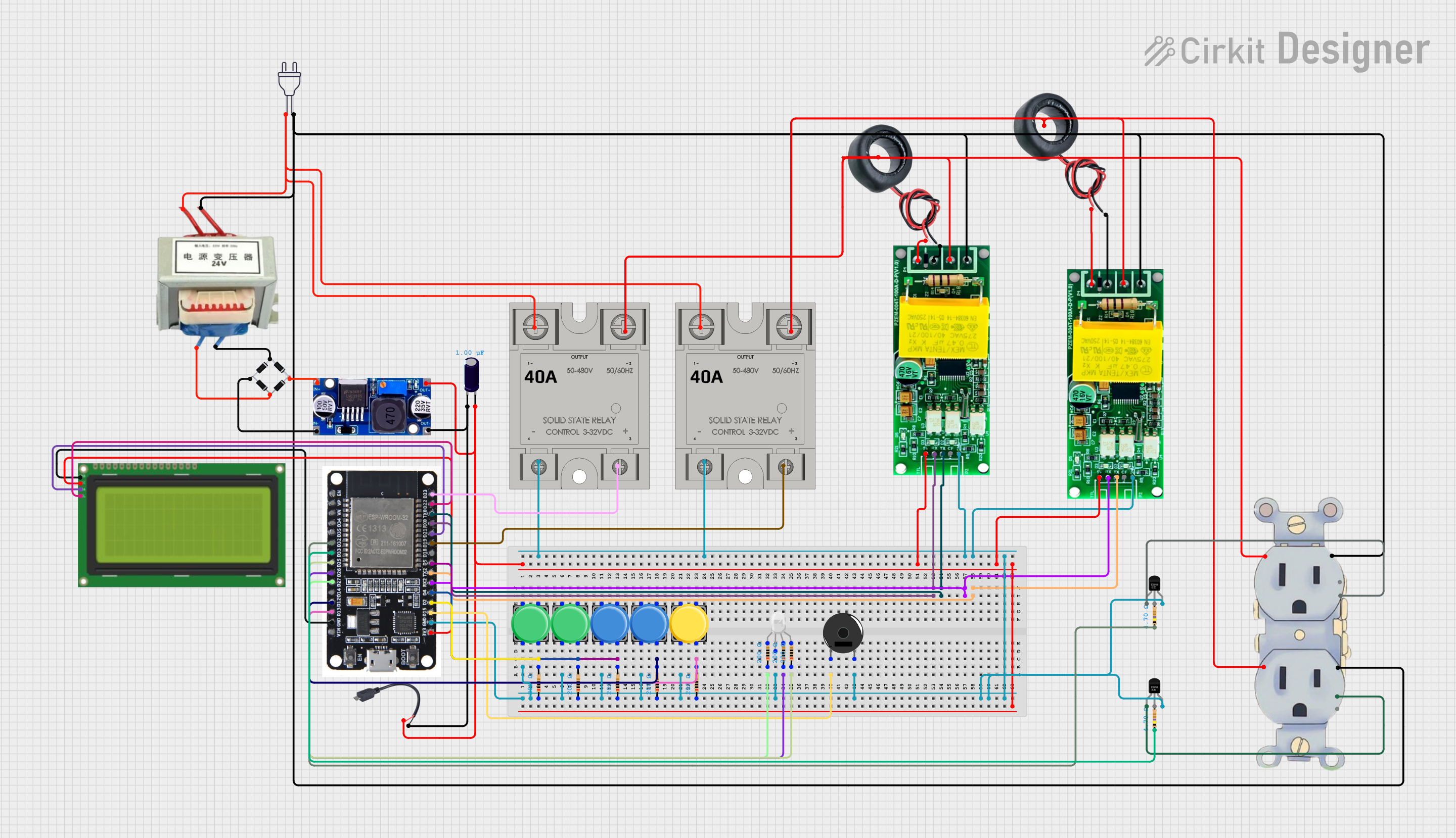
Circuit Documentation
Summary
This circuit is designed to monitor and control electrical parameters using an ESP32 microcontroller. It includes various sensors, relays, and an LCD display to provide real-time data and control functionalities. The circuit also integrates with the Blynk platform for remote monitoring and control.
Component List
ESP32
- Description: A powerful microcontroller with Wi-Fi and Bluetooth capabilities.
- Pins: EN, VP, VN, D34, D35, D32, D33, D25, D26, D27, D14, D12, D13, GND, VIN, 3V3, D15, D2, D4, RX2, TX2, D5, D18, D19, D21, RX0, TX0, D22, D23, BOOT
Grounding Receptacle Outlet 15A 250V~
- Description: A grounding receptacle outlet for 15A, 250V~.
- Pins: life, GND, Life
Bridge Rectifier
- Description: Converts AC to DC.
- Pins: Source_in-, source_out-, source_out+, source_in+
LM2596
- Description: A DC-DC buck converter.
- Pins: IN, OUT
Electrolytic Capacitor
- Description: Stores electrical energy.
- Pins: -, +
- Properties: Capacitance: 0.000001 Farads
Power 220V
- Description: Power source.
- Pins: hot wire, neutral wire
SSR-40A
- Description: Solid State Relay.
- Pins: -, +, Lin, Lout
Micro USB to Cable (2 Pin)
- Description: Micro USB to 2-pin cable.
- Pins: Micro USB, +, -
LCD 20x4 I2C
- Description: 20x4 character LCD with I2C interface.
- Pins: GND, 5v, SCA, SCL
PZEM-004T AC
- Description: AC power monitor.
- Pins: 5V, RX, TX, CF, GND
Pushbutton
- Description: A simple pushbutton.
- Pins: Pin 2, Pin 1, Pin 3, Pin 4
Resistor
- Description: Limits current flow.
- Pins: pin1, pin2
- Properties: Resistance: 200 Ohms
COIL
- Description: Inductor coil.
- Pins: +, -
RGB LED (Wokwi compatible)
- Description: RGB LED.
- Pins: R, COM, G, B
Piezo Buzzer
- Description: Emits sound.
- Pins: pin 1, pin 2
DS18B20
- Description: Temperature sensor.
- Pins: VDD, DQ, GND
Wiring Details
ESP32
- GND: Connected to GND of various components.
- D2: Connected to Pin 4 of a pushbutton through a resistor.
- D4: Connected to Pin 4 of a pushbutton through a resistor.
- D5: Connected to Pin 4 of a pushbutton through a resistor.
- D12: Connected to Pin 4 of a pushbutton through a resistor.
- D13: Connected to Pin 4 of a pushbutton through a resistor.
- D15: Connected to pin 1 of the Piezo Buzzer.
- D19: Connected to + of an SSR-40A.
- D21: Connected to SCA of the LCD 20x4 I2C.
- D22: Connected to SCL of the LCD 20x4 I2C.
- D23: Connected to + of an SSR-40A.
- D25: Connected to pin2 of a resistor, which is connected to B of the RGB LED.
- D26: Connected to pin2 of a resistor, which is connected to G of the RGB LED.
- D27: Connected to pin2 of a resistor, which is connected to R of the RGB LED.
- RX0: Connected to RX of a PZEM-004T AC.
- TX0: Connected to TX of a PZEM-004T AC.
- RX2: Connected to RX of another PZEM-004T AC.
- TX2: Connected to TX of another PZEM-004T AC.
- 3V3: Connected to 5v of the LCD 20x4 I2C.
Grounding Receptacle Outlet 15A 250V~
- life: Connected to hot wire of power 220v and Lin of SSR-40A.
- GND: Connected to Source_in- of the Bridge Rectifier.
Bridge Rectifier
- Source_in-: Connected to GND of the Grounding Receptacle Outlet 15A 250V~.
- source_in+: Connected to Life of the Grounding Receptacle Outlet 15A 250V~.
- source_out-: Connected to IN of LM2596.
- source_out+: Connected to IN of LM2596.
LM2596
- IN: Connected to source_out- and source_out+ of the Bridge Rectifier.
- OUT: Connected to + of the Electrolytic Capacitor and + of the Micro USB to Cable (2 Pin).
Electrolytic Capacitor
- +: Connected to OUT of LM2596.
- -: Connected to OUT of LM2596.
Micro USB to Cable (2 Pin)
- +: Connected to OUT of LM2596.
- -: Connected to OUT of LM2596.
LCD 20x4 I2C
- GND: Connected to GND of the ESP32.
- 5v: Connected to 3V3 of the ESP32.
- SCA: Connected to D21 of the ESP32.
- SCL: Connected to D22 of the ESP32.
PZEM-004T AC
- 5V: Connected to + of the Micro USB to Cable (2 Pin).
- RX: Connected to RX0 of the ESP32.
- TX: Connected to TX0 of the ESP32.
- GND: Connected to GND of the ESP32.
Pushbutton
- Pin 2: Connected to pin1 of a resistor.
- Pin 4: Connected to pin2 of a resistor, which is connected to D2, D4, D5, D12, and D13 of the ESP32.
Resistor
- pin1: Connected to Pin 2 of the pushbutton.
- pin2: Connected to Pin 4 of the pushbutton and various pins of the ESP32.
COIL
- +: Connected to PZEM-004T AC.
- -: Connected to PZEM-004T AC.
RGB LED (Wokwi compatible)
- R: Connected to pin2 of a resistor, which is connected to D27 of the ESP32.
- G: Connected to pin2 of a resistor, which is connected to D26 of the ESP32.
- B: Connected to pin2 of a resistor, which is connected to D25 of the ESP32.
- COM: Connected to GND of the ESP32.
Piezo Buzzer
- pin 1: Connected to D15 of the ESP32.
- pin 2: Connected to GND of the ESP32.
DS18B20
- VDD: Connected to outlet.
- DQ: Not connected.
- GND: Connected to GND of the ESP32.
Documented Code
#include <BlynkSimpleEsp32.h>
#include <LiquidCrystal_I2C.h>
#include <Wire.h>
#include <DallasTemperature.h>
#include <OneWire.h>

// Blynk Authentication Token
#define BLYNK_TEMPLATE_ID "Your Template ID"
#define BLYNK_DEVICE_NAME "Your Device Name"
#define BLYNK_AUTH_TOKEN "Your Auth Token"

// LCD and Temperature Sensor Setup
LiquidCrystal_I2C lcd(0x27, 20, 4); // Address 0x27, 20x4 LCD
#define ONE_WIRE_BUS 4              // DS18B20 data pin
OneWire oneWire(ONE_WIRE_BUS);
DallasTemperature sensors(&oneWire);

// Pins for PZEM, Relays, and RGB
#define RELAY1_PIN 23
#define