
Arduino UNO Flood Management System with Ultrasonic Sensor and Wi-Fi Connectivity
View and Edit Project In Cirkit Designer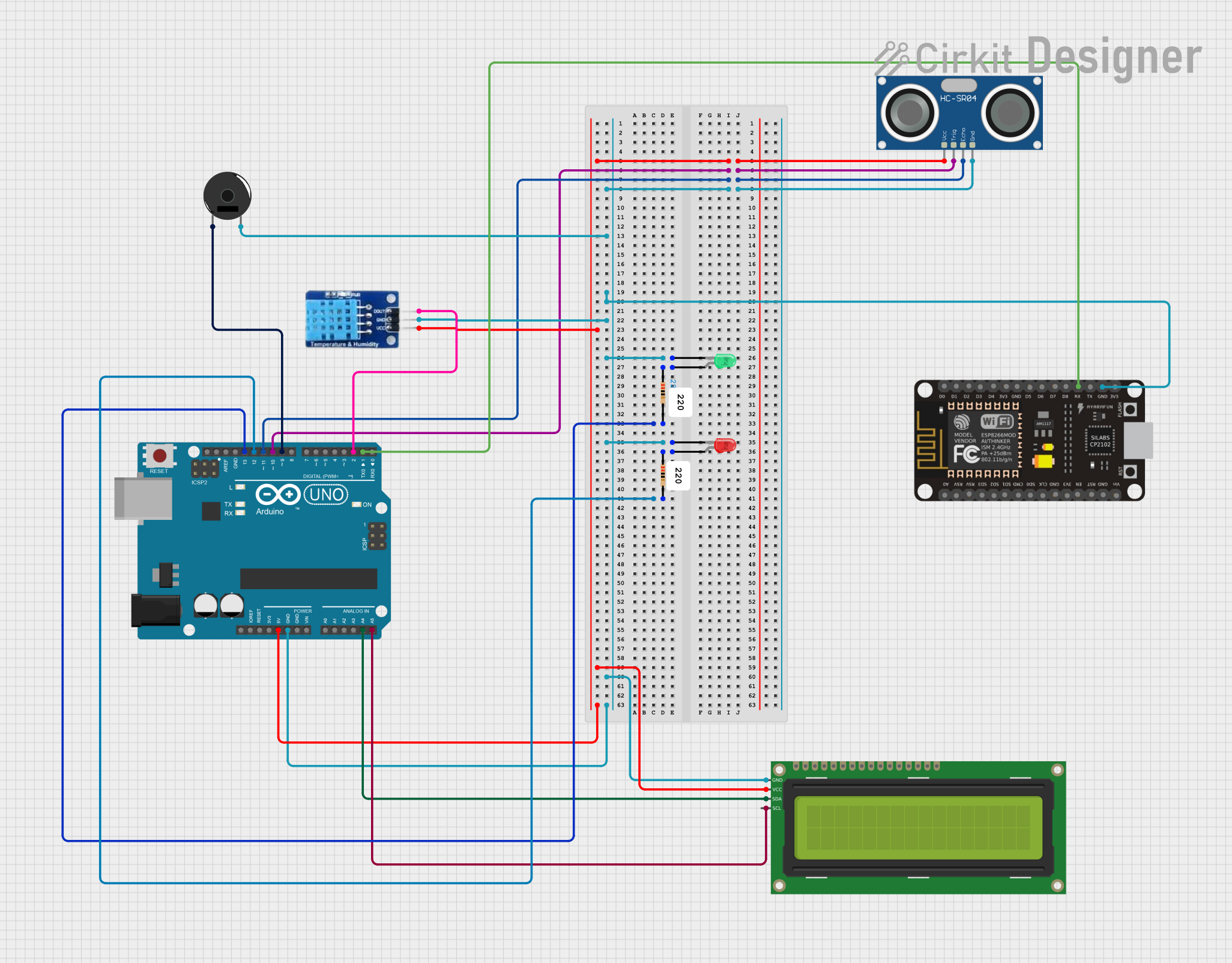
Circuit Documentation
Summary
This document provides a detailed overview of a flood management device circuit. The circuit includes various sensors, an LCD display, LEDs, a piezo buzzer, and microcontrollers. The Arduino UNO serves as the primary microcontroller, interfacing with the sensors and actuators to monitor environmental conditions and provide alerts.
Component List
HC-SR04 Ultrasonic Sensor
- Pins: VCC, TRIG, ECHO, GND
- Description: Measures distance using ultrasonic waves.
- Purpose: Used to detect water level.
DHT11
- Pins: DATA, GND, VCC
- Description: Temperature and humidity sensor.
- Purpose: Measures ambient temperature and humidity.
16x2 I2C LCD
- Pins: GND, VCC, SDA, SCL
- Description: 16x2 character LCD with I2C interface.
- Purpose: Displays sensor readings and alerts.
Piezo Buzzer
- Pins: pin 1, pin 2
- Description: Emits sound when activated.
- Purpose: Provides audible alerts.
Resistor (200 Ohms)
- Pins: pin1, pin2
- Description: Limits current.
- Purpose: Used in series with LEDs to limit current.
Resistor (220 Ohms)
- Pins: pin1, pin2
- Description: Limits current.
- Purpose: Used in series with LEDs to limit current.
Arduino UNO
- Pins: UNUSED, IOREF, Reset, 3.3V, 5V, GND, Vin, A0, A1, A2, A3, A4, A5, SCL, SDA, AREF, D13, D12, D11, D10, D9, D8, D7, D6, D5, D4, D3, D2, D1, D0
- Description: Microcontroller board based on the ATmega328P.
- Purpose: Main controller for the circuit.
LED: Two Pin (red)
- Pins: cathode, anode
- Description: Red LED.
- Purpose: Indicates status.
LED: Two Pin (green)
- Pins: cathode, anode
- Description: Green LED.
- Purpose: Indicates status.
esp8266 nodemcu
- Pins: D0, D1, D2, D3, D4, 3V3, GND, D5, D6, D7, D8, RX, TX, A0, RSV, SD3, SD2, SD1, CMD, SD0, CLK, EN, RST, VIN
- Description: Wi-Fi module.
- Purpose: Provides wireless communication.
Wiring Details
HC-SR04 Ultrasonic Sensor
- VCC connected to 5V on Arduino UNO
- TRIG connected to D10 on Arduino UNO
- ECHO connected to D11 on Arduino UNO
- GND connected to GND on Arduino UNO
DHT11
- DATA connected to D2 on Arduino UNO
- GND connected to GND on Arduino UNO
- VCC connected to 5V on Arduino UNO
16x2 I2C LCD
- GND connected to GND on Arduino UNO
- VCC connected to 5V on Arduino UNO
- SDA connected to A4 on Arduino UNO
- SCL connected to A5 on Arduino UNO
Piezo Buzzer
- pin 1 connected to D9 on Arduino UNO
- pin 2 connected to GND on Arduino UNO
Resistor (200 Ohms)
- pin1 connected to anode of LED: Two Pin (green)
- pin2 connected to D13 on Arduino UNO
Resistor (220 Ohms)
- pin1 connected to anode of LED: Two Pin (red)
- pin2 connected to D12 on Arduino UNO
LED: Two Pin (red)
- cathode connected to GND on Arduino UNO
- anode connected to pin1 of Resistor (220 Ohms)
LED: Two Pin (green)
- cathode connected to GND on Arduino UNO
- anode connected to pin1 of Resistor (200 Ohms)
esp8266 nodemcu
- GND connected to GND on Arduino UNO
- RX connected to D1 on Arduino UNO
Documented Code
#include <Wire.h> // Library for I2C communication
#include <LiquidCrystal_I2C.h> // Library for LCD
#include <SoftwareSerial.h>
#include <DHT.h>
#include <NewPing.h>

#define TRIGGER_PIN 10 // Arduino pin tied to trigger pin on the ultrasonic sensor.
#define ECHO_PIN 11 // Arduino pin tied to echo pin on the ultrasonic sensor.
// #define MAX_DISTANCE 200
NewPing sonar(TRIGGER_PIN, ECHO_PIN);
SoftwareSerial B(0,1);
LiquidCrystal_I2C lcd = LiquidCrystal_I2C(0x3F, 16, 2); // Change to (0x27,16,2) for 16x2 LCD.my address is (0x3F)

const int trigPin = 10;
int button = 2;
int buttonstate = 0 , led_num = 0;
const int echoPin = 11;
#define DHTPIN 3
const int buzzer = 9;
int led1 = 13;
int led2 = 12;
#define DHTTYPE    DHT11
DHT dht(DHTPIN, DHTTYPE);
float distance, duration;
int safetydistance = 4;

void setup(){
  Serial.begin(9600);
 B.begin(9600);
 lcd.init();
 dht.begin();
 pinMode(button, INPUT);
 pinMode(buzzer, OUTPUT);
 lcd.backlight();
 pinMode(trigPin, OUTPUT);
 pinMode(echoPin, INPUT);
 pinMode(led1, OUTPUT);
 pinMode(led2, OUTPUT);
 lcd.setCursor(0,0);
 lcd.print("FLOOD MANAGEMENT");
 lcd.setCursor(0,1);
 lcd.print("     DEVICE    ");
 delay(2000);
  lcd.clear();
}

void loop() {
  buttonstate = digitalRead(button);
  float t = dht.readTemperature();
  float h = dht.readHumidity();
  if (isnan(h) || isnan(t)) {
    Serial.println("Failed to read from DHT sensor!");
  }
  digitalWrite(trigPin, LOW);
  delayMicroseconds(2);
  digitalWrite(trigPin, HIGH);
  delayMicroseconds(10);
  digitalWrite(trigPin, LOW);
  duration = pulseIn(echoPin, HIGH);
  duration = sonar.ping_median(10);
  distance = sonar.ping_cm();

  Serial.println(distance);
  Serial.println("cm");
  digitalWrite(led2, HIGH);
 digitalWrite(led1, LOW);
//if (val == 1){
// led_num = led_num + 1;

if (buttonstate == LOW){
  lcd.clear();
   lcd.setCursor(0,0);
 lcd.print("Water Level : ");
 lcd.setCursor(0,1);
 lcd.print("Depth : ");
 lcd.print(distance);
 lcd.print("cm");

}

else if (buttonstate == HIGH){
  lcd.clear();
   lcd.setCursor(0,0);
  lcd.print("Temp: ");
  lcd.print(t);
  lcd.print((char)223);
  lcd.print("C");
  lcd.setCursor(0,1);
  lcd.print("Humidity: ");
  lcd.print(h);
  lcd.print("%");
  //led_num = 0;
}
 delay(300);

 if (distance <= safetydistance){
  digitalWrite(buzzer, HIGH);
  digitalWrite(led1, HIGH);
  digitalWrite(led2, LOW);
  B.print("Flood Alert! There may be chances of flood. Please take necessary precutions. Thank You !");
  delay(1000);

}
else{
  digitalWrite(buzzer, LOW);

}
}
This code initializes the sensors and actuators, reads data from the sensors, and displays the information on the LCD. It also provides an audible alert if the water level exceeds a predefined safety distance.