
ESP32 and SIM900A Based Smart Home Automation with Wi-Fi and GSM Control
View and Edit Project In Cirkit Designer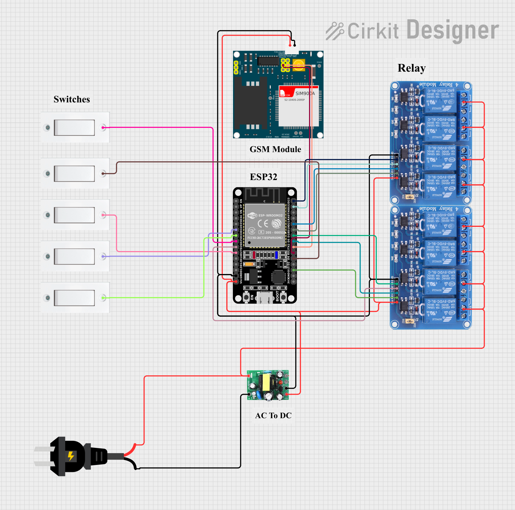
Circuit Documentation
Summary
This document provides a detailed overview of a circuit that includes various components such as relays, switches, an ESP32 microcontroller, an AC source, and a SIM900A module. The circuit is designed to control multiple relays using the ESP32 microcontroller, with inputs from flush switches and power supplied by an AC source and a DC converter.
Component List
Relay 4 Channel 5v
- Description: A relay module with 4 channels, each capable of switching high voltage devices.
- Pins: GND, IN1, IN2, IN3, IN4, VCC, COM1, COM2, COM3, COM4, NO1, NO2, NO3, NO4, NC1, NC2, NC3, NC4
actodc
- Description: A DC converter module.
- Pins: 12v, -, 5v, live, neutral
Flush Switch
- Description: A simple switch with two pins.
- Pins: GND, VCC
ESP32 (30 pin)
- Description: A microcontroller with 30 pins, used for various control and communication tasks.
- Pins: EN, VP, VN, D34, D35, D32, D33, D25, D26, D27, D14, D12, D13, GND, Vin, D23, D22, TX0, RX0, D21, D19, D18, D5, TX2, RX2, D4, D2, D15, 3V3
AC source
- Description: An AC power source.
- Pins: +, -
SIM900A
- Description: A GSM module for communication.
- Pins: GND, DB9-3 (RXD), DB9-2 (TXD), 5V, 3VR, 5VR, 3VT, 5VT, VCC, Ring, RESTART, RESET, STATUS
Comment
- Description: A placeholder component for comments.
- Pins: None
Wiring Details
Relay 4 Channel 5v
GND connected to:
- actodc (-)
- SIM900A (GND)
- ESP32 (GND)
VCC connected to:
- actodc (5v)
- SIM900A (5V)
- ESP32 (Vin)
IN1 connected to ESP32 (D23)
IN2 connected to ESP32 (D22)
IN3 connected to ESP32 (D21)
IN4 connected to ESP32 (D19)
COM1, COM2, COM3, COM4 connected to:
- actodc (live)
- AC source (+)
actodc
- connected to:
- Relay 4 Channel 5v (GND)
- SIM900A (GND)
- ESP32 (GND)
5v connected to:
- Relay 4 Channel 5v (VCC)
- SIM900A (5V)
- ESP32 (Vin)
live connected to:
- Relay 4 Channel 5v (COM1, COM2, COM3, COM4)
- AC source (+)
neutral connected to AC source (-)
Flush Switch
- VCC connected to:
- ESP32 (D32)
- ESP32 (D33)
- ESP32 (D25)
- ESP32 (D27)
- ESP32 (D4)
ESP32 (30 pin)
GND connected to:
- actodc (-)
- Relay 4 Channel 5v (GND)
- SIM900A (GND)
Vin connected to:
- actodc (5v)
- Relay 4 Channel 5v (VCC)
- SIM900A (5V)
D32 connected to Flush Switch (VCC)
D33 connected to Flush Switch (VCC)
D25 connected to Flush Switch (VCC)
D27 connected to Flush Switch (VCC)
D4 connected to Flush Switch (VCC)
D23 connected to Relay 4 Channel 5v (IN1)
D22 connected to Relay 4 Channel 5v (IN2)
D21 connected to Relay 4 Channel 5v (IN3)
D19 connected to Relay 4 Channel 5v (IN4)
TX2 connected to SIM900A (5VR)
RX2 connected to SIM900A (5VT)
AC source
+ connected to:
- actodc (live)
- Relay 4 Channel 5v (COM1, COM2, COM3, COM4)
- connected to actodc (neutral)
SIM900A
GND connected to:
- actodc (-)
- Relay 4 Channel 5v (GND)
- ESP32 (GND)
5V connected to:
- actodc (5v)
- Relay 4 Channel 5v (VCC)
- ESP32 (Vin)
5VR connected to ESP32 (TX2)
5VT connected to ESP32 (RX2)
Code Documentation
ESP32 (30 pin)
void setup() {
  // put your setup code here, to run once:

}

void loop() {
  // put your main code here, to run repeatedly:

}
This code is a basic template for the ESP32 microcontroller. The setup function is called once when the microcontroller starts, and the loop function runs continuously. You can add your specific logic to control the relays and handle inputs from the flush switches in these functions.