
Arduino UNO Controlled Robotic Arm with Multiple Motors and Servos
View and Edit Project In Cirkit Designer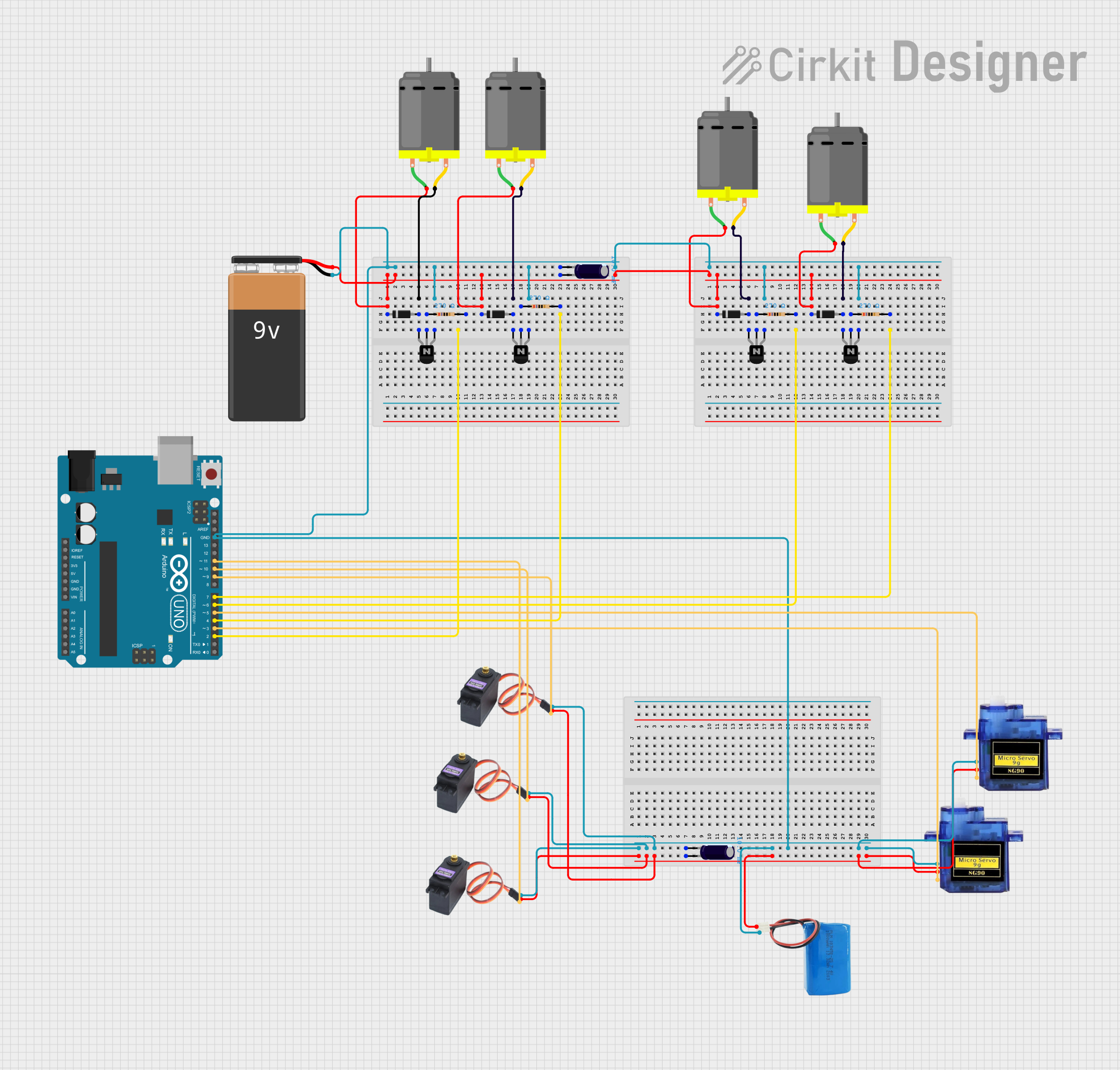
Circuit Documentation
Summary
This circuit involves an Arduino UNO microcontroller, multiple DC motors, servos, a 9V battery, a 5V battery, resistors, diodes, capacitors, and NPN transistors. The Arduino UNO controls the servos and motors, while the power is supplied by the batteries. The circuit also includes various passive components to ensure proper operation and protection of the active components.
Component List
Micro servo 9G
- Pins: GND, +5V, PWM
- Description: A small servo motor used for precise control of angular position.
DC Motor
- Pins: pin 1, pin 2
- Description: A motor that converts electrical energy into mechanical motion.
Arduino UNO
- Pins: UNUSED, IOREF, Reset, 3.3V, 5V, GND, Vin, A0, A1, A2, A3, A4, A5, SCL, SDA, AREF, D13, D12, D11, D10, D9, D8, D7, D6, D5, D4, D3, D2, D1, D0
- Description: A microcontroller board based on the ATmega328P.
MG996R
- Pins: GND, VCC, SIG
- Description: A high-torque servo motor.
9V Battery
- Pins: -, +
- Description: A battery providing 9V power supply.
5V Battery
- Pins: positive, negative
- Description: A battery providing 5V power supply.
Electrolytic Capacitor
- Pins: -, +
- Description: A capacitor with a capacitance of 0.01 Farads.
Resistor
- Pins: pin1, pin2
- Description: A resistor with a resistance of 270 Ohms.
Diode
- Pins: cathode, anode
- Description: A diode used for current direction control.
NPN Transistor (EBC)
- Pins: emitter, base, collector
- Description: A transistor used for switching and amplification.
Wiring Details
Micro servo 9G
- GND: Connected to GND of Arduino UNO.
- +5V: Connected to +5V of 5V battery.
- PWM: Connected to D5 (first servo) and D3 (second servo) of Arduino UNO.
DC Motor
- pin 1: Connected to cathode of diodes and + of 9V battery.
- pin 2: Connected to collector of NPN transistors.
Arduino UNO
- GND: Connected to GND of 9V battery, GND of 5V battery, and GND of servos.
- D2: Not connected.
- D3: Connected to PWM of second Micro servo 9G.
- D4: Connected to pin2 of a resistor.
- D5: Connected to PWM of first Micro servo 9G.
- D6: Connected to pin2 of a resistor.
- D7: Connected to pin2 of a resistor.
- D9: Connected to SIG of MG996R servo.
- D10: Connected to SIG of MG996R servo.
- D11: Connected to SIG of MG996R servo.
MG996R
- GND: Connected to GND of 5V battery.
- VCC: Connected to +5V of 5V battery.
- SIG: Connected to D9, D10, and D11 of Arduino UNO.
9V Battery
- -: Connected to GND of Arduino UNO.
- +: Connected to pin 1 of DC motors and cathode of diodes.
5V Battery
- negative: Connected to GND of Arduino UNO.
- positive: Connected to +5V of servos.
Electrolytic Capacitor
- -: Connected to GND of Arduino UNO.
- +: Connected to pin 1 of DC motors and cathode of diodes.
Resistor
- pin1: Connected to base of NPN transistors.
- pin2: Connected to D4, D6, and D7 of Arduino UNO.
Diode
- cathode: Connected to pin 1 of DC motors and + of 9V battery.
- anode: Connected to collector of NPN transistors.
NPN Transistor (EBC)
- emitter: Connected to GND of Arduino UNO.
- base: Connected to pin1 of resistors.
- collector: Connected to pin 2 of DC motors and anode of diodes.
Code Documentation
#include <Wire.h>
#include <Adafruit_PWMServoDriver.h>

// Initialize the PWM driver
Adafruit_PWMServoDriver pwm = Adafruit_PWMServoDriver();

void setup() {
  pwm.begin();
  pwm.setPWMFreq(60);  // Set the frequency to 60 Hz
}

void loop() {
  // Example: Turn servo on channel 0 to the middle position
  pwm.setPWM(0, 0, 2048);
  delay(1000);

  // Turn servo on channel 0 to the minimum position
  pwm.setPWM(0, 0, 409);
  delay(1000);

  // Turn servo on channel 0 to the maximum position
  pwm.setPWM(0, 0, 3687);
  delay(1000);
}
This code initializes the PWM driver and sets the frequency to 60 Hz. In the loop, it moves a servo connected to channel 0 to three different positions: middle, minimum, and maximum, with a delay of 1 second between each movement.