
Solar-Powered Environmental Monitoring System with Automatic Transfer Switch and ESP32 Control
View and Edit Project In Cirkit Designer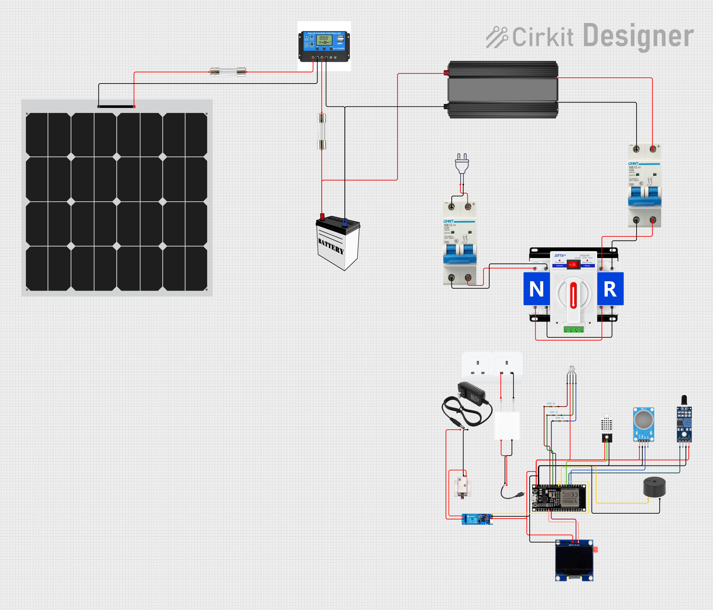
Circuit Documentation
Summary of the Circuit
This circuit appears to be a power management system that integrates solar power with a traditional 220V power supply. It includes a dual power automatic transfer switch to select between solar and 220V inputs, a charge controller for managing solar power input, a power inverter to convert DC to AC, and a 12V battery for energy storage. The circuit also features various safety components such as circuit breakers and fuses. Additionally, there are sensors and a microcontroller (ESP32) for monitoring and control purposes, along with a 5V adapter to power low-voltage components.
Component List
Circuit Breakers
- Protects the circuit from overcurrent by breaking the connection when the current exceeds a safe level.
Dual Power Automatic Transfer Switch
- Automatically switches between two power sources, in this case, solar and 220V.
Solar Panel
- Converts sunlight into electrical energy to be used by the circuit or stored in the battery.
Charge Controller
- Manages the charge to the battery from the solar panel and provides connections for a load.
Power Inverter
- Converts DC power from the battery or solar panel to AC power for household devices.
Power 220V
- Represents the traditional household power supply at 220V.
Fuses
- Provides overcurrent protection by breaking the circuit when current exceeds a specified level.
Sockets
- Interface for connecting household devices to the power supply.
5V Adapter
- Converts AC power to a 5V DC supply for low-voltage components.
ESP32 Microcontroller
- A programmable device used to control and monitor various components in the circuit.
MQ-2 Gas Sensor
- Detects gases like LPG, propane, methane, and smoke.
SHT113 Flame Sensor
- Detects the presence of a flame or fire.
Buzzer
- Emits an audible alert in response to certain conditions detected by the system.
Micro USB to Cable (2 Pin)
- Provides a connection for power to be supplied via a micro USB interface.
LED: Four Pin
- A multi-color LED with separate pins for red, green, and blue cathodes and a common anode.
Resistors
- Limits the current flow through components, such as LEDs, to prevent damage.
12V Battery
- Stores electrical energy for use by the circuit when solar power is insufficient or unavailable.
12V Power Supply
- Provides a stable 12V DC power source for components like the relay module and solenoid lock.
12V Solenoid Lock
- An electrically-controlled lock that can be opened or closed by the circuit.
Relay Module 5V-30V
- An electrically operated switch that allows the microcontroller to control higher power loads.
DHT22 Temperature and Humidity Sensor
- Measures ambient temperature and humidity.
OLED 1.3" Display
- A small screen for displaying information such as sensor readings or system status.
Wiring Details
Circuit Breakers
- Two circuit breakers are used to protect both the solar panel input and the 220V power supply.
Dual Power Automatic Transfer Switch
- Connects to both the solar panel and the 220V power supply, switching between them as needed.
Solar Panel
- Wired to the charge controller to provide solar power to the system.
Charge Controller
- Manages power between the solar panel, battery, and load. It is connected to the solar panel, battery, and power inverter.
Power Inverter
- Converts DC from the battery to AC and is protected by a circuit breaker and a fuse.
Power 220V
- The traditional power supply is connected through a circuit breaker for protection.
Fuses
- Placed in series with the solar panel and battery to protect against overcurrent.
Sockets
- Connected to the 5V adapter to provide power to low-voltage components.
5V Adapter
- Converts 220V AC power to 5V DC, supplying power to the microcontroller and other low-voltage components.
ESP32 Microcontroller
- Central control unit for the circuit, interfacing with sensors, the OLED display, and controlling the relay module and buzzer.
MQ-2 Gas Sensor
- Connected to the ESP32 for gas detection.
SHT113 Flame Sensor
- Connected to the ESP32 for flame detection.
Buzzer
- Wired to the ESP32 to provide an audible alert.
Micro USB to Cable (2 Pin)
- Provides a 5V power supply to the ESP32 microcontroller.
LED: Four Pin
- Connected to the ESP32 through resistors to limit current and prevent damage.
Resistors
- Three 500 Ohm resistors are used to limit current to the multi-color LED.
12V Battery
- Provides backup power to the power inverter and is charged by the solar panel through the charge controller.
12V Power Supply
- Supplies power to the relay module and the solenoid lock.
12V Solenoid Lock
- Controlled by the relay module, allowing the ESP32 to lock or unlock it.
Relay Module 5V-30V
- Allows the ESP32 to control high-power devices like the solenoid lock.
DHT22 Temperature and Humidity Sensor
- Connected to the ESP32 to provide environmental data.
OLED 1.3" Display
- Displays information from the ESP32, such as sensor readings and system status.
Documented Code
No code was provided for the microcontroller (ESP32). The documentation of the code would typically include descriptions of the functions, libraries used, and the logic behind the code's operation. It would also detail how the code interacts with the various sensors and output devices in the circuit. Since no code is available, this section cannot be completed.