Cirkit Designer
Your all-in-one circuit design IDE
Home /
Project Documentation
Arduino Mega 2560-Controlled Robotic Vehicle with GPS and Wireless Communication
Circuit Documentation
Summary
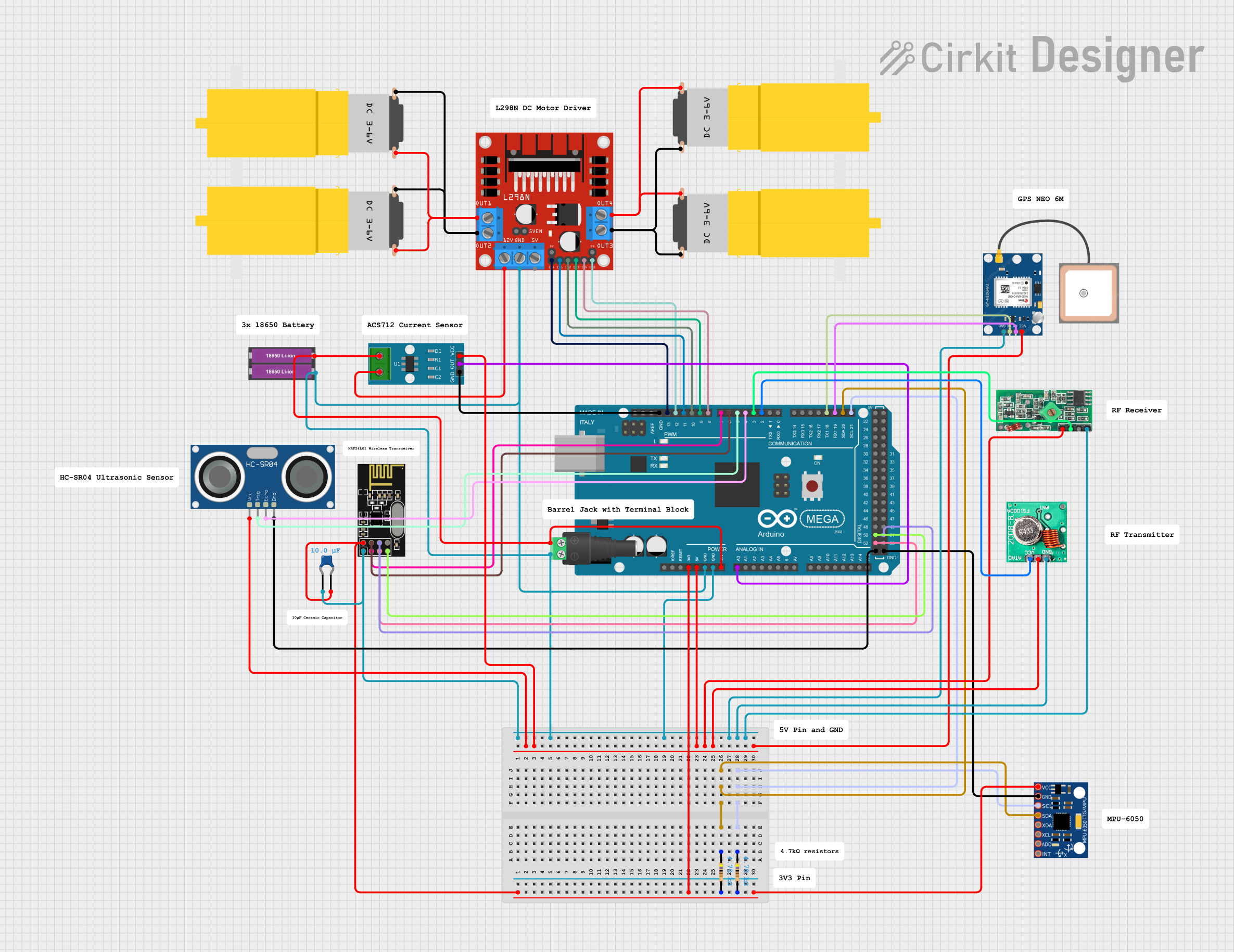
This circuit is designed to interface various sensors and modules with an Arduino Mega 2560 microcontroller. It includes motor drivers for controlling hobby motors, a current sensor for monitoring electrical current, a GPS module for location tracking, an ultrasonic sensor for distance measurement, RF communication modules for wireless data transmission, and an MPU-6050 for motion sensing. The circuit is powered by a 18650 Li-ion battery pack and includes necessary passive components like resistors and capacitors for stable operation.
Component List
Microcontroller
- Arduino Mega 2560: A microcontroller board based on the ATmega2560 with numerous digital and analog I/O pins.
Sensors and Modules
- ACS712 Current Sensor 5A 20A 30A: A hall-effect-based linear current sensor capable of measuring both AC and DC currents.
- HC-SR04 Ultrasonic Sensor: An ultrasonic ranging module for distance measurement.
- GPS NEO 6M: A GPS module for obtaining geographical location data.
- NRF24L01: A 2.4GHz wireless transceiver module for RF communication.
- MPU-6050: A 6-axis gyroscope and accelerometer module for motion tracking.
- 433 MHz RF Receiver Module: A radio frequency receiver for wireless communication at 433 MHz.
- FS1000A 433MHz RF Transmitter: A radio frequency transmitter for wireless communication at 433 MHz.
Power Components
- 18650 Li-ion Battery x 2: A battery pack consisting of two 18650 Li-ion cells.
- 2.1mm Barrel Jack with Terminal Block: A power connector for the battery pack.
Motor Drivers
- L298N DC motor driver: A dual H-bridge motor driver for controlling the direction and speed of DC motors.
Passive Components
- Ceramic Capacitor: A 0.01 µF capacitor for noise suppression and voltage smoothing.
- Resistor: Two 4.7 kΩ resistors used for pull-up on I2C lines.
Motors
- Motor amarillo motorreductor hobby: Four hobby motors with gear reduction for driving mechanical loads.
Wiring Details
Arduino Mega 2560
- Digital I/O: Connected to various modules for control signals (e.g., ultrasonic sensor, motor driver, RF modules).
- Analog Input: A0 connected to the ACS712 current sensor output.
- I2C: SDA and SCL connected to the MPU-6050 with pull-up resistors.
- 3.3V: Powers the NRF24L01 module and MPU-6050.
- 5V: Powers the HC-SR04 ultrasonic sensor, ACS712 current sensor, GPS NEO 6M, and RF modules.
- GND: Common ground for all components.
- VIN: Connected to the positive terminal of the battery pack through the barrel jack.
ACS712 Current Sensor
- VCC: Connected to 5V from the Arduino.
- OUT: Connected to A0 on the Arduino for current measurement.
- GND: Connected to common ground.
HC-SR04 Ultrasonic Sensor
- VCC: Connected to 5V from the Arduino.
- TRIG: Connected to a digital I/O pin on the Arduino for triggering distance measurement.
- ECHO: Connected to a digital I/O pin on the Arduino for receiving distance information.
- GND: Connected to common ground.
GPS NEO 6M
- VCC: Connected to 5V from the Arduino.
- RX: Connected to a TX pin on the Arduino for sending data to the GPS module.
- TX: Connected to an RX pin on the Arduino for receiving data from the GPS module.
- GND: Connected to common ground.
NRF24L01
- VCC (3V): Connected to 3.3V from the Arduino with a capacitor in parallel for stability.
- GND: Connected to common ground.
- CE, CSN: Connected to digital I/O pins on the Arduino for control.
- SCK, MISO, MOSI: Connected to the SPI pins on the Arduino for data communication.
MPU-6050
- VCC: Connected to 3.3V from the Arduino.
- GND: Connected to common ground.
- SDA, SCL: Connected to the I2C pins on the Arduino with pull-up resistors.
RF Modules
- 433 MHz RF Receiver Module: VCC connected to 5V, DATA to a digital I/O pin, and GND to common ground.
- FS1000A 433MHz RF Transmitter: VCC connected to 5V, DATA to a digital I/O pin, GND to common ground, and ANT to an antenna.
L298N DC motor driver
- IN1-IN4: Connected to digital I/O pins on the Arduino for motor control.
- ENB, ENA: Connected to PWM-capable digital I/O pins on the Arduino for speed control.
- OUT1-OUT4: Connected to the motors.
- 12V: Connected to the positive terminal of the battery pack through the ACS712 sensor.
- GND: Connected to common ground.
Motors
- vcc: Connected to the motor driver outputs.
- GND: Connected to the motor driver outputs.
Documented Code
sketch.ino
void setup() {
  // put your setup code here, to run once:

}

void loop() {
  // put your main code here, to run repeatedly:

}
documentation.txt
(No additional documentation provided for the code)