
ESP32-Based Obstacle-Avoiding Robot with Ultrasonic Sensors and MPU-6050
View and Edit Project In Cirkit Designer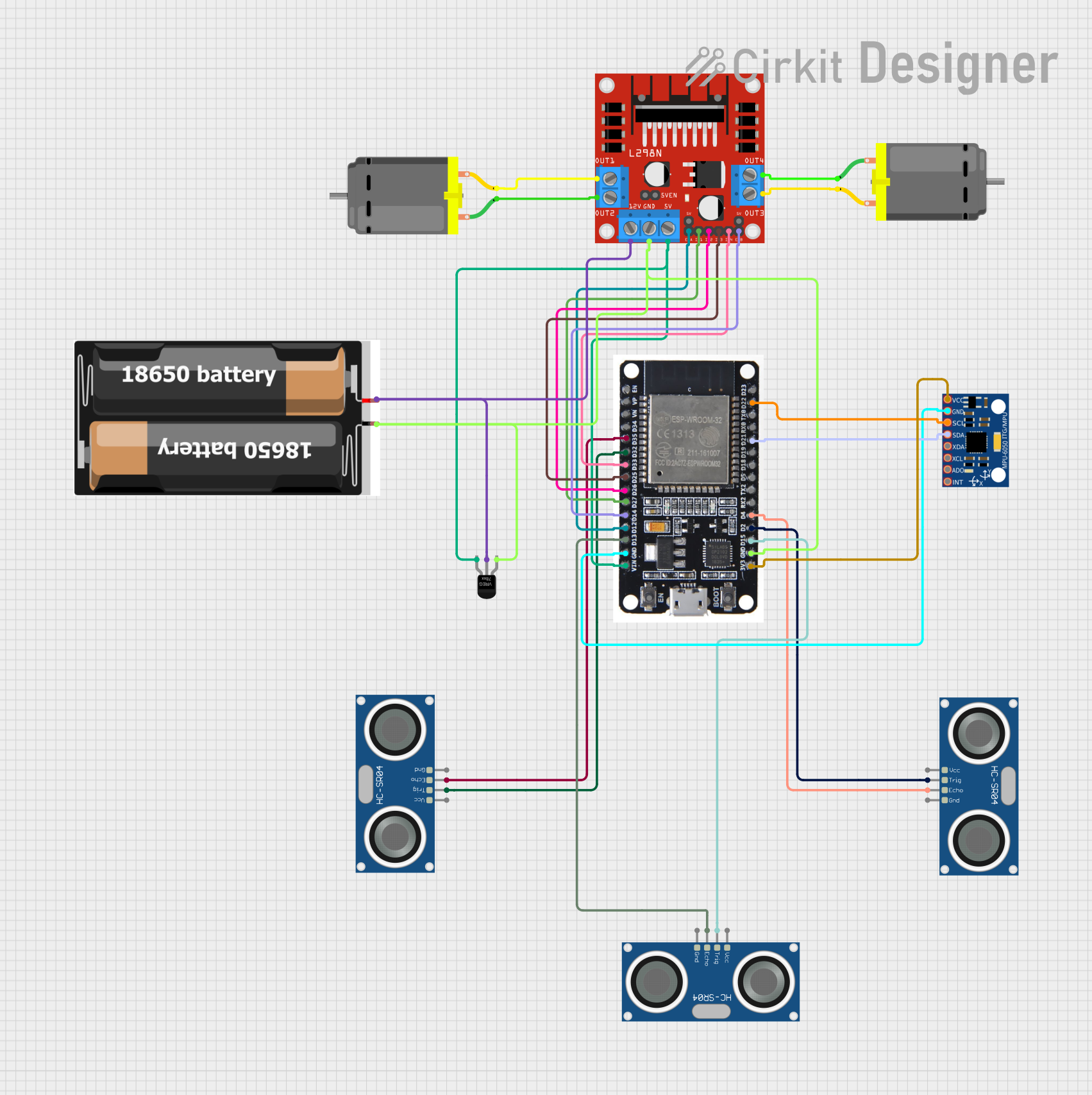
Circuit Documentation
Summary
This document provides a detailed overview of a circuit designed to control a robotic vehicle. The circuit includes an ESP32 microcontroller, multiple sensors (MPU-6050 and HC-SR04 Ultrasonic Sensors), a motor driver (L298N), and DC motors. The ESP32 is programmed to read sensor data and control the motors to navigate through a maze.
Component List
L298N DC Motor Driver
- Description: Dual H-Bridge motor driver for controlling two DC motors.
- Pins: OUT1, OUT2, 12V, GND, 5V, OUT3, OUT4, 5V-ENA-JMP-I, 5V-ENA-JMP-O, +5V-J1, +5V-J2, ENA, IN1, IN2, IN3, IN4, ENB
DC Motor
- Description: Standard DC motor.
- Pins: pin 1, pin 2
MPU-6050
- Description: 6-axis motion tracking device.
- Pins: VCC, GND, SCL, SDA, XDA, XCL, AD0, INT
HC-SR04 Ultrasonic Sensor
- Description: Ultrasonic distance sensor.
- Pins: VCC, TRIG, ECHO, GND
ESP32
- Description: Microcontroller with Wi-Fi and Bluetooth capabilities.
- Pins: EN, VP, VN, D34, D35, D32, D33, D25, D26, D27, D14, D12, D13, GND, VIN, 3V3, D15, D2, D4, RX2, TX2, D5, D18, D19, D21, RX0, TX0, D22, D23, BOOT
2x 18650
- Description: Battery pack consisting of two 18650 cells.
- Pins: vcc, gnd
Voltage Regulator
- Description: Regulates voltage to a stable level.
- Pins: GND, IN, OUT
Wiring Details
L298N DC Motor Driver
- IN1 connected to D27 of ESP32
- IN2 connected to D26 of ESP32
- IN3 connected to D25 of ESP32
- IN4 connected to D33 of ESP32
- ENA connected to D12 of ESP32
- ENB connected to D14 of ESP32
- 5V connected to OUT of Voltage Regulator
- GND connected to GND of ESP32, GND of Voltage Regulator, and gnd of 2x 18650
- 12V connected to vcc of 2x 18650
- OUT1 connected to pin 2 of DC Motor
- OUT2 connected to pin 1 of DC Motor
- OUT3 connected to pin 2 of DC Motor
- OUT4 connected to pin 1 of DC Motor
DC Motor
- pin 1 connected to OUT2 of L298N DC Motor Driver
- pin 2 connected to OUT1 of L298N DC Motor Driver
- pin 1 connected to OUT4 of L298N DC Motor Driver
- pin 2 connected to OUT3 of L298N DC Motor Driver
MPU-6050
- VCC connected to 3V3 of ESP32
- GND connected to GND of ESP32
- SCL connected to D22 of ESP32
- SDA connected to D21 of ESP32
HC-SR04 Ultrasonic Sensor
- TRIG connected to D32 of ESP32
- ECHO connected to D35 of ESP32
- TRIG connected to D15 of ESP32
- ECHO connected to D13 of ESP32
- TRIG connected to D2 of ESP32
- ECHO connected to D4 of ESP32
ESP32
- VIN connected to OUT of Voltage Regulator
- GND connected to GND of Voltage Regulator, GND of MPU-6050, and GND of L298N DC Motor Driver
- 3V3 connected to VCC of MPU-6050
2x 18650
- vcc connected to IN of Voltage Regulator
- gnd connected to GND of Voltage Regulator
Voltage Regulator
- IN connected to vcc of 2x 18650
- OUT connected to VIN of ESP32 and 5V of L298N DC Motor Driver
- GND connected to gnd of 2x 18650
Documented Code
ESP32 Code
#include <Wire.h>
#include <Adafruit_MPU6050.h>
#include <Adafruit_Sensor.h>
#include <Ultrasonic.h>

#define TRIG_PIN1 5
#define ECHO_PIN1 18
#define TRIG_PIN2 17
#define ECHO_PIN2 16
#define TRIG_PIN3 4
#define ECHO_PIN3 0

#define IN1 25
#define IN2 26
#define IN3 27
#define IN4 14
#define ENA 12
#define ENB 13

Ultrasonic ultrasonic1(TRIG_PIN1, ECHO_PIN1);
Ultrasonic ultrasonic2(TRIG_PIN2, ECHO_PIN2);
Ultrasonic ultrasonic3(TRIG_PIN3, ECHO_PIN3);

Adafruit_MPU6050 mpu;

void setup() {
  Serial.begin(115200);

  // Initialize MPU6050
  if (!mpu.begin()) {
    Serial.println("Failed to find MPU6050 chip");
    while (1) {
      delay(10);
    }
  }

  // Initialize motor driver pins
  pinMode(IN1, OUTPUT);
  pinMode(IN2, OUTPUT);
  pinMode(IN3, OUTPUT);
  pinMode(IN4, OUTPUT);
  pinMode(ENA, OUTPUT);
  pinMode(ENB, OUTPUT);

  // Set initial motor speed
  analogWrite(ENA, 255);
  analogWrite(ENB, 255);
}

void loop() {
  // Read ultrasonic sensors
  long distance1 = ultrasonic1.read();
  long distance2 = ultrasonic2.read();
  long distance3 = ultrasonic3.read();

  // Read MPU6050
  sensors_event_t a, g, temp;
  mpu.getEvent(&a, &g, &temp);

  // Maze-solving logic
  if (distance1 < 20) {
    // Obstacle ahead, turn right
    digitalWrite(IN1, LOW);
    digitalWrite(IN2, HIGH);
    digitalWrite(IN3, HIGH);
    digitalWrite(IN4, LOW);
  } else if (distance2 < 20) {
    // Obstacle on the left, turn right
    digitalWrite(IN1, LOW);
    digitalWrite(IN2, HIGH);
    digitalWrite(IN3, HIGH);
    digitalWrite(IN4, LOW);
  } else if (distance3 < 20) {
    // Obstacle on the right, turn left
    digitalWrite(IN1, HIGH);
    digitalWrite(IN2, LOW);
    digitalWrite(IN3, LOW);
    digitalWrite(IN4, HIGH);
  } else {
    // Move forward
    digitalWrite(IN1, HIGH);
    digitalWrite(IN2, LOW);
    digitalWrite(IN3, HIGH);
    digitalWrite(IN4, LOW);
  }

  delay(100);
}
DC Motor Code
void setup() {
  // put your setup code here, to run once:
}

void loop() {
  // put your main code here, to run repeatedly:
}
This document provides a comprehensive overview of the circuit, including the components used, their wiring details, and the code running on the microcontroller.