Cirkit Designer
Your all-in-one circuit design IDE
Home /
Project Documentation
Arduino-Controlled Flame Detection System with Motorized Response and Infrared Temperature Sensing
Circuit Documentation
Summary
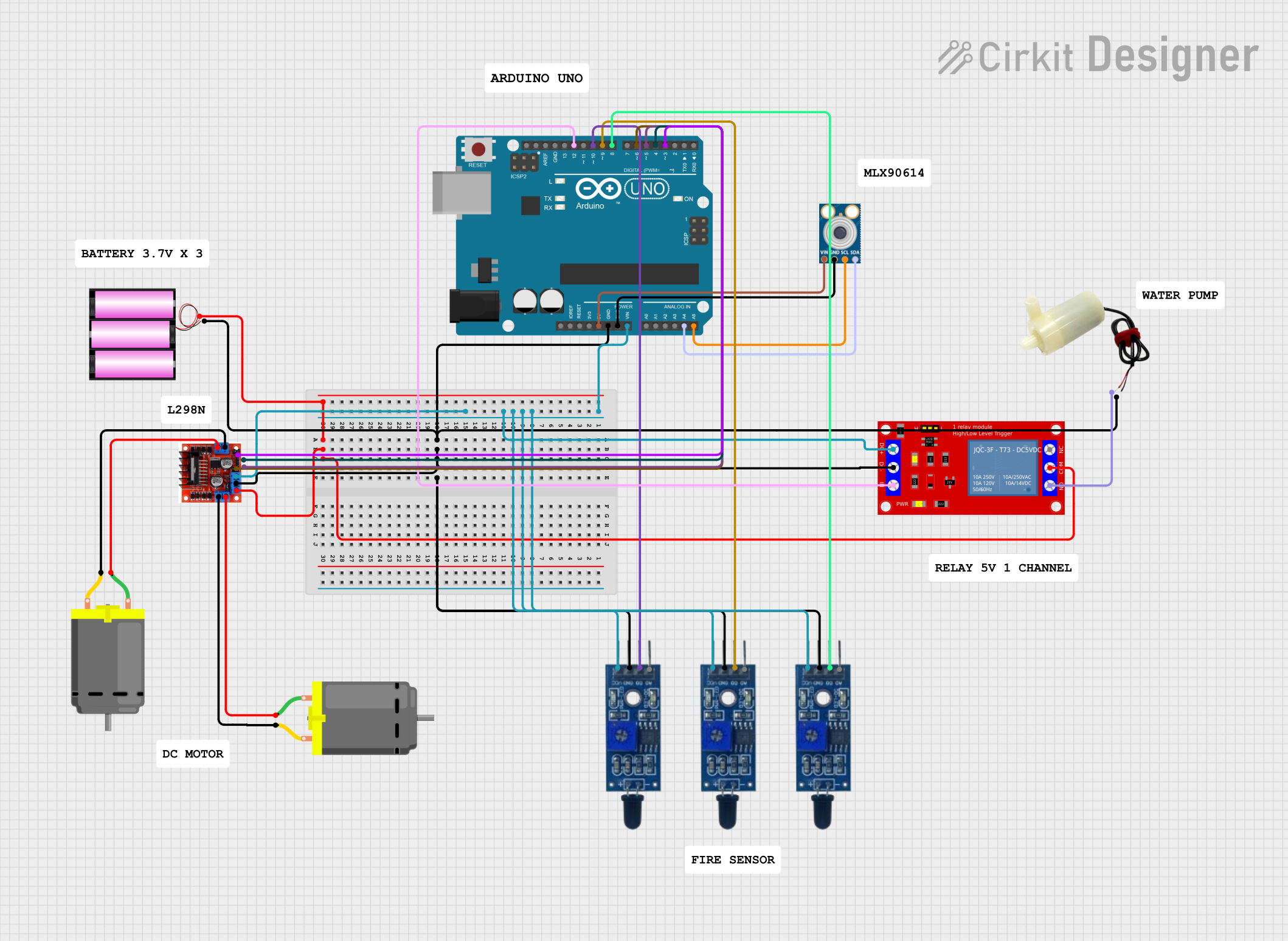
This circuit is designed to control two DC motors and a mini water pump, with the ability to detect flames using three flame sensors. It is controlled by an Arduino UNO microcontroller, which also interfaces with an MLX90614 infrared temperature sensor. The motors are driven by an L298N Motor Driver, and the water pump is controlled via a 5V relay module. The power is supplied by a 12V battery, which powers the motor driver and the relay module, while the Arduino and sensors are powered by the Arduino's regulated 5V output.
Component List
DC Motors
- DC Motor 1: A motor that converts electrical energy into mechanical energy.
- DC Motor 2: Another instance of the motor for additional mechanical action.
Flame Sensors
- Flame Sensor 1: A sensor that detects the presence of a flame or fire.
- Flame Sensor 2: A second sensor for detecting flames, allowing for multiple detection points.
- Flame Sensor 3: A third sensor for comprehensive flame detection coverage.
Relay Module
- 1 Channel 5V Relay Module: An electrically operated switch that controls the mini water pump.
Water Pump
- 5V Mini Water Pump: A pump that moves water when activated by the relay.
Motor Driver
- L298N Motor Driver Controller Board Module: A module that drives the DC motors, allowing for control of speed and direction.
Power Supply
- Battery 12V: The main power source for the circuit.
Microcontroller
- Arduino UNO: The central controller that manages the operation of the circuit components.
Temperature Sensor
- MLX90614: An infrared temperature sensor for non-contact temperature measurements.
Comments
- Comment: Additional notes or labels that may be included in the circuit for documentation or clarification purposes.
Wiring Details
DC Motor 1
- Connected to the L298N Motor Driver's Output A.
DC Motor 2
- Connected to the L298N Motor Driver's Output B.
Flame Sensor 1
- VCC connected to Arduino UNO's Vin.
- GND connected to the common ground net.
- D0 connected to Arduino UNO's D10.
Flame Sensor 2
- VCC connected to Arduino UNO's Vin.
- GND connected to the common ground net.
- D0 connected to Arduino UNO's D9.
Flame Sensor 3
- VCC connected to Arduino UNO's Vin.
- GND connected to the common ground net.
- D0 connected to Arduino UNO's D8.
1 Channel 5V Relay Module
- VCC+ connected to Arduino UNO's Vin.
- VCC- (GND) connected to the common ground net.
- IN connected to Arduino UNO's D12.
- N.O. connected to the 5V mini water pump's positive pin.
- COM connected to the battery's positive terminal.
5V Mini Water Pump
- Positive pin connected to the relay module's N.O.
- Negative pin connected to the common ground net.
L298N Motor Driver
- +12V Power connected to the battery's positive terminal.
- +5V Power connected to Arduino UNO's Vin.
- Ground connected to the common ground net.
- Input 1 connected to Arduino UNO's D6.
- Input 2 connected to Arduino UNO's D5.
- Input 3 connected to Arduino UNO's D4.
- Input 4 connected to Arduino UNO's D3.
Battery 12V
- Positive terminal connected to the L298N Motor Driver's +12V Power and the relay module's COM.
- Negative terminal connected to the common ground net.
Arduino UNO
- Vin connected to the Flame Sensors' VCC and the relay module's VCC+.
- GND connected to the common ground net.
- Digital pins D3, D4, D5, D6, D8, D9, D10, and D12 connected to the L298N Motor Driver and Flame Sensors as specified above.
- 5V pin connected to the MLX90614's VIN.
- A4 (SDA) connected to the MLX90614's SDA.
- A5 (SCL) connected to the MLX90614's SCL.
MLX90614
- VIN connected to Arduino UNO's 5V.
- GND connected to the common ground net.
- SDA connected to Arduino UNO's A4.
- SCL connected to Arduino UNO's A5.
Documented Code
Arduino UNO Code (sketch.ino)
void setup() {
  // put your setup code here, to run once:

}

void loop() {
  // put your main code here, to run repeatedly:

}
Note: The provided code is a template and does not contain any functional code. It needs to be populated with the logic to control the motors, read sensors, and actuate the relay based on the sensor inputs.