
Circuit Documentation
Summary
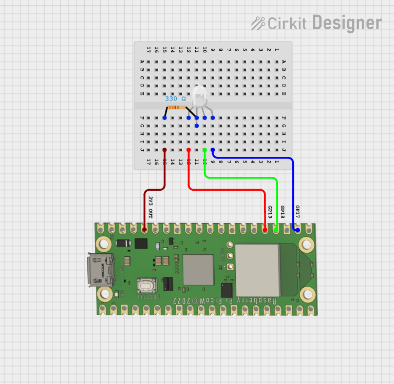
This circuit integrates a Raspberry Pi Pico W microcontroller with an RGB LED and a resistor. The microcontroller is programmed to interact with various peripherals, including sensors and an LCD display, and to connect to a Wi-Fi network for MQTT communication. The RGB LED is controlled by the microcontroller to display different colors, and a resistor is used to limit the current to the LED.
Component List
Raspberry Pi Pico W
- Description: A microcontroller board based on the RP2040 microcontroller, featuring Wi-Fi connectivity.
- Pins: VBUS, VSYS, GP16, GP17, GND, GP18, GP19, GP20, GP21, GP22, RUN, GP26, GP27, GP28, ADC_VREF, 3V3 OUT, 3V3_EN, GP0, GP1, GP2, GP3, GP4, GP5, GP6, GP7, GP15, GP14, GP13, GP12, GP11, GP10, GP9, GP8.
RGB LED (Wokwi compatible)
- Description: A four-pin RGB LED capable of displaying a range of colors by mixing red, green, and blue light.
- Pins: R, COM, G, B.
Resistor
- Description: A passive two-terminal electrical component that implements electrical resistance as a circuit element.
- Resistance: 330 Ohms.
Wiring Details
Raspberry Pi Pico W
- GP17: Connected to the blue pin (B) of the RGB LED.
- GP18: Connected to the green pin (G) of the RGB LED.
- GP19: Connected to the red pin (R) of the RGB LED.
- 3V3 OUT: Connected to pin1 of the Resistor.
RGB LED (Wokwi compatible)
- R (Red): Connected to GP19 of the Raspberry Pi Pico W.
- G (Green): Connected to GP18 of the Raspberry Pi Pico W.
- B (Blue): Connected to GP17 of the Raspberry Pi Pico W.
- COM (Common Anode): Connected to pin2 of the Resistor.
Resistor
- pin1: Connected to 3V3 OUT of the Raspberry Pi Pico W.
- pin2: Connected to the COM pin of the RGB LED.
Documented Code
import machine
import network
import time
import dht
from machine import Pin
from machine import I2C
from lcd_api import LcdApi
from i2c_lcd import I2cLcd
from time import sleep
import utime
from umqtt.simple import MQTTClient

SSID = "project"
PASSWORD = "12345678"
MQTT_BROKER = "test.mosquitto.org"
MQTT_TOPIC = "JN_17102024"

# Set up the DHT11 sensor
dht_pin = machine.Pin(4)  # Change this to the GPIO pin you connected the DHT11 data pin to
dht_sensor = dht.DHT11(dht_pin)
degree_celsius_symbol = chr(223)

ldr_pin = machine.ADC(26)  # LDR sensor (light detection)
microwave_sensor = machine.Pin(16, machine.Pin.IN)
light = machine.Pin(6, machine.Pin.OUT)  # LED 1
fan = machine.Pin(7, machine.Pin.OUT)  # LED 2
button1 = machine.Pin(8, machine.Pin.IN)
button2 = machine.Pin(9, machine.Pin.IN)
light.value(1)
fan.value(1)
current_mode = None

I2C_ADDR = 0x27
totalRows = 2
totalColumns = 16
sensor = dht.DHT11(Pin(6))

i2c = I2C(1, sda=machine.Pin(2), scl=machine.Pin(3), freq=400000)
lcd = I2cLcd(i2c, I2C_ADDR, totalRows, totalColumns)

lcd.clear()
lcd.putstr("     WELCOME      ")
lcd.move_to(0,1)
lcd.putstr("________________")
time.sleep(1)
lcd.clear()
lcd.putstr("SELECT MODE")
time.sleep(1)

def connect_wifi():
    wlan = network.WLAN(network.STA_IF)
    wlan.active(True)
    if not wlan.isconnected():
        print('Connecting to Wi-Fi...')
        lcd.clear()
        lcd.putstr("CONNECTING")
        lcd.move_to(0,1)
        lcd.putstr("WIFI....")
        time.sleep(2)
        wlan.connect(SSID, PASSWORD)
        while not wlan.isconnected():
            time.sleep(1)
    print('Connected to Wi-Fi:', wlan.ifconfig())
    lcd.clear()
    lcd.putstr("WIFI")
    lcd.move_to(0,1)
    lcd.putstr("CONNECTED")
    time.sleep(2)

# Function to handle MQTT messages
def mqtt_callback(topic, msg):
    print((topic, msg))

    # Check message and control LED
    if msg == b'a':
        light.value(0)
    elif msg == b'b':
        light.value(1)
    elif msg == b'c':
        fan.value(0)
    elif msg == b'd':
        fan.value(1)

# Connect to the MQTT broker and subscribe to the topic
def connect_mqtt():
    client = MQTTClient('raspberry_pi_pico', MQTT_BROKER)
    lcd.clear()
    lcd.putstr("MQTT")
    lcd.move_to(0,1)
    lcd.putstr("CONNECTING..")
    time.sleep(2)
    client.set_callback(mqtt_callback)
    client.connect()
    client.subscribe(MQTT_TOPIC)
    print(f"Subscribed to topic {MQTT_TOPIC}")
    lcd.clear()
    lcd.putstr("MQTT")
    lcd.move_to(0,1)
    lcd.putstr("CONNECTED")
    time.sleep(2)

    while True:
        client.check_msg()  # Continuously check for incoming messages
        time.sleep(1)
        if button2.value() == 0:
            break

def sensor_control():
    while True:
        movement_detected = microwave_sensor.value()
        dht_sensor.measure()
        temperature_c = dht_sensor.temperature()
        temperature_string = f'{temperature_c}{degree_celsius_symbol}C'
        humidity = dht_sensor.humidity()
        print(movement_detected)
        if movement_detected == 1:
            lcd.clear()
            lcd.putstr("MOVEMENT")
            lcd.putstr(" DET")
            time.sleep(2)
            for i in range(60, 0, -1):   # Reverse loop from 100 to 1
                if i>=40:
                    fan.value(0)
                lcd.clear()
                lcd.putstr("Time:")
                lcd.putstr(str(i))  # Countdown
                lcd.putstr(" SECS")
                lcd.move_to(0,1)
                lcd.putstr("T:")
                lcd.putstr(str(temperature_string))
                lcd.putstr(" H:")
                lcd.putstr(str(humidity))
                lcd.putstr("%")
                time.sleep(1)
                light_value = ldr_pin.read_u16()
                if light_value <= 10000:
                    light.value(0)
                if light_value >= 20000:
                    light.value(1)
                if temperature_c >= 35:
                    fan.value(0)
                if temperature_c <= 34:
                    fan.value(1)
                if button1.value() == 0:
                    break

        if movement_detected == 0:
            lcd.clear()
            lcd.putstr("NO MOVEMENT")
            light.value(1)
            fan.value(1)
        if button1.value() == 0:
            break

# Main function
while True:
    if button1.value() == 0:
        current_mode = "app_mode"
    if current_mode == "app_mode":
        lcd.clear()
        lcd.putstr("APP MODE")
        lcd.move_to(0,1)
        lcd.putstr("IOT CONTROL")
        time.sleep(1)
        connect_wifi()
        connect_mqtt()
    if button2.value() == 0:
        current_mode = "automatic_mode"
    if current_mode == "automatic_mode":
        lcd.clear()
        lcd.putstr("AUTOMATIC MODE")
        lcd.move_to(0,1)
        lcd.putstr("SENSOR CONTROL")
        time.sleep(1)
        sensor_control()
The code provided is for the Raspberry Pi Pico W microcontroller. It includes functionality for connecting to a Wi-Fi network, handling MQTT messages, controlling an RGB LED, and reading from sensors. The code also includes a user interface with an LCD display to show status messages and sensor readings.